Marten Electric 電気テン @ Home
Vintage audio gear connoisseur, computer enthusiast, time nut, music lover, vintage games gamer, nerd, tinkerer and shady electronic projects makerZilog Z80 CPU PLCC44 to DIP40 adapter
Introduction
I have originally designed this adaptor for Z80 microcomputer project and CPU tester, but this turn out so well that I have now posted all schematic, gerber files and documentation to fellow enthusiast such as yourself :) Perhaps (and I hope) content in this obscured corner of interwebs will inspire you to start your own projects.
I have found out that Z80 adaptor for QFP44 to DIP40 and PLCC44 to DIP40 packages are non existent on market and this little board would be handy, if you collect Zilog Z80 CPU's or just wanna have a play with different revisions/packages. Design of my adaptor PCB was inspired by random PLCC to DIP adaptor used usually for EEPROM programmers etc. You can find tons of these gadgets on interwebs.
I will buy one of those fancy random PLCC to DIP adaptor or any other PLCC adaptors and it will all work you say.... WRONG!
Zilog Z80 in QFP and PLCC package has different pinout to standard and can not be used in one to one replacement. For starters QFP nad PLCC has 44 pins and DIP package only 40. Check out Product specification sheet and let the evidence guide your senses ☉ ‿ ⚆.
You can use adaptor in conjuction with Zilog Z80 CPU NOP Tester - NOP operation tester to test Zilog Z80 CPU and compatible clones.
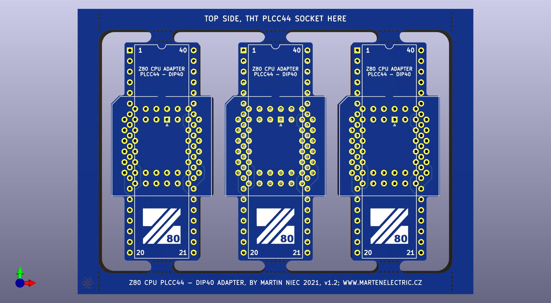
PCB was designed in a tenet that form follows function and nothing more. Nothing special to mention about PLCC44 footprint, throughole package was chosed as it's easier to solder at home and pins don't colide. Machined DIP headers are strongly recommended as classic might ruin your precious DIP socket.
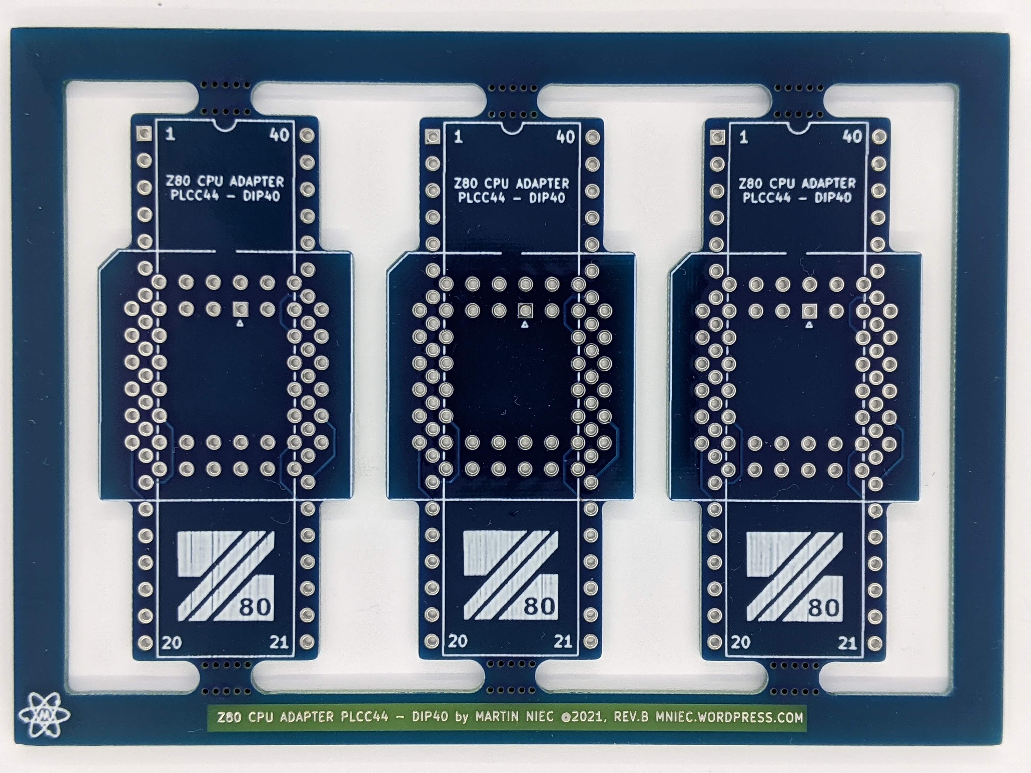
These boards look absolutely gorgeous in standard blue solder mask because hey! Zilog was all about blue! I can advise you where to buy connectors, I bought mine on Ali.
⊂(◉‿◉)つ
Except where otherwise noted, content on this site is licensed under a Creative Commons Attribution 4.0 International license. CC-BY-4.0
I have created content on this website free to use for personal, educational and commercial purposes. If you like or use my work, please mention me or perhaps consider a donation.
| or |
... but if you feel like getting something for nothing isn't your cup of tea (completely understandable) (ಥ﹏ಥ) and a prefer to support me and get something back in return, then you can purchase directly on my eBay or Tindie shop. However if you are still up for an adventure */in very positive way/* (and are happy to have PCB's made yourself in your favourite PCB house - PCBWay is highly recommended), then carry on, download gerber files and have fun! ( ͡° ͜ʖ ͡°)


EDA preview
click on pictures to enlarge
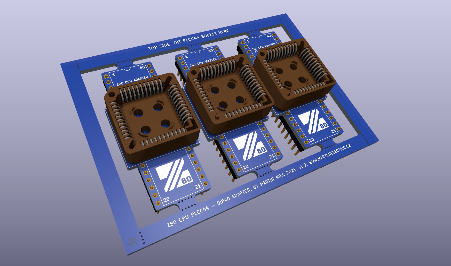
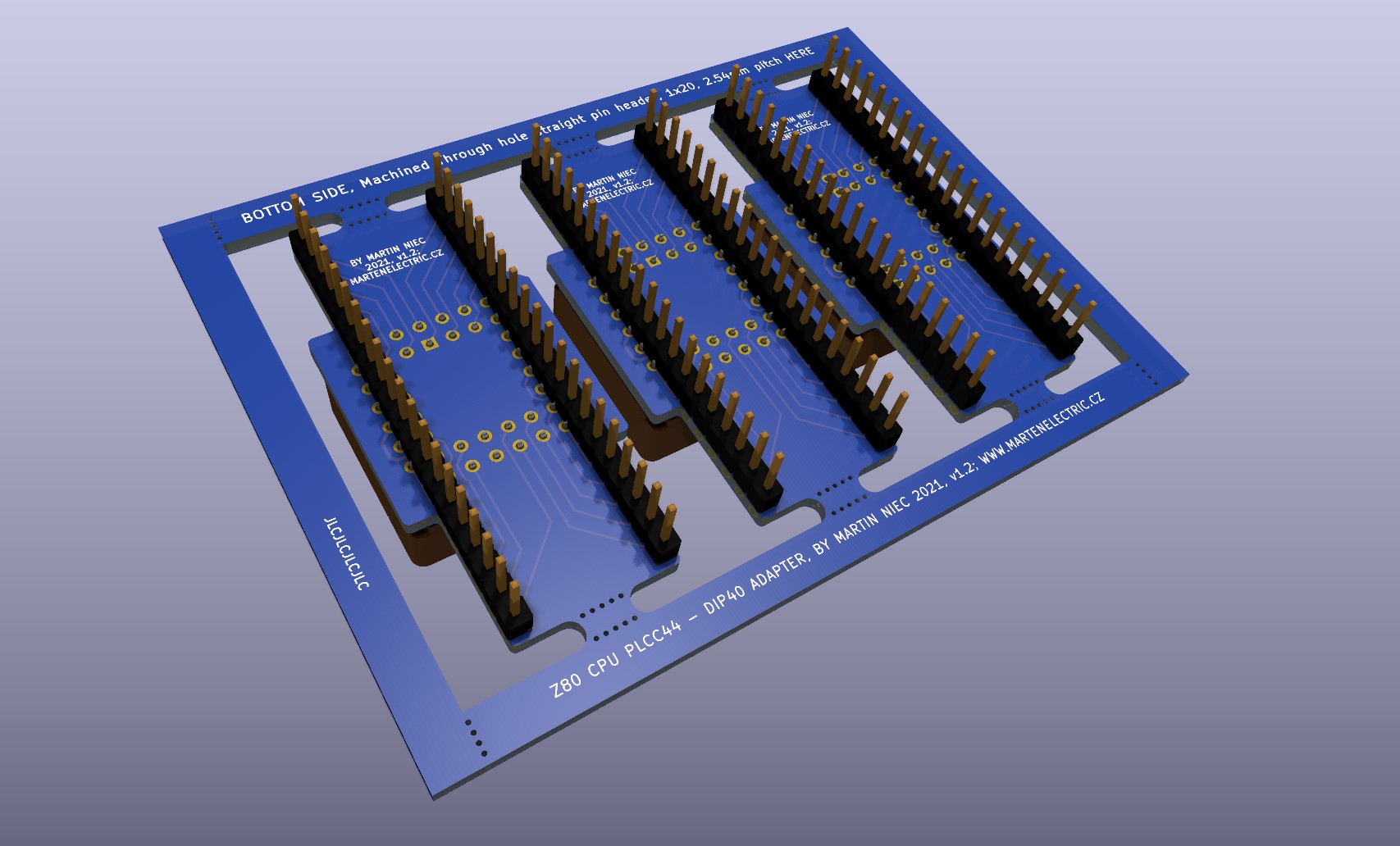
3d render v1.20
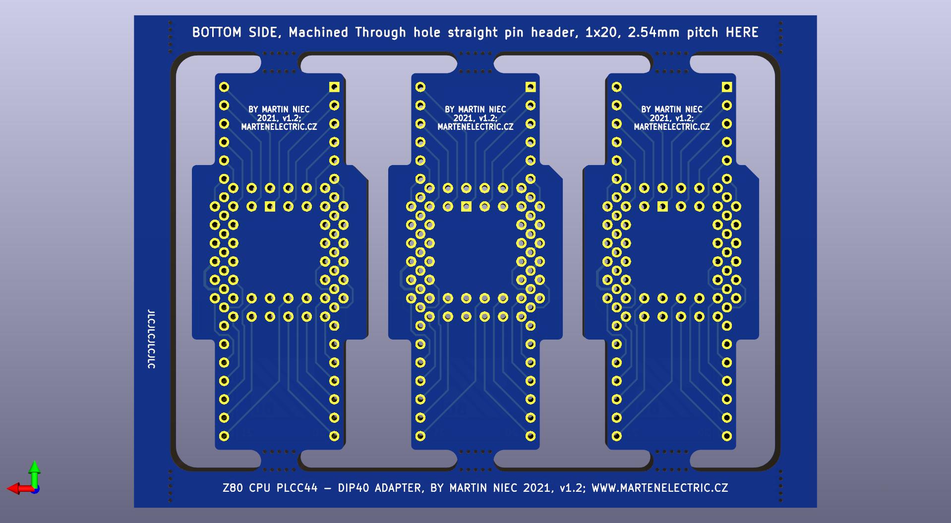
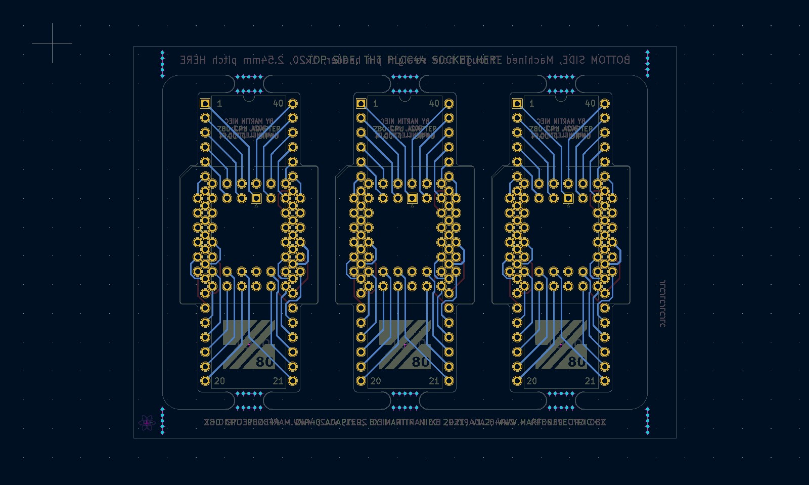
PCB design layout v1.20

Specifications
Board Type: Adapter
Board Material: FR4-Standard Tg 130-140C Epoxy Glass Composite
Layers: Double sided
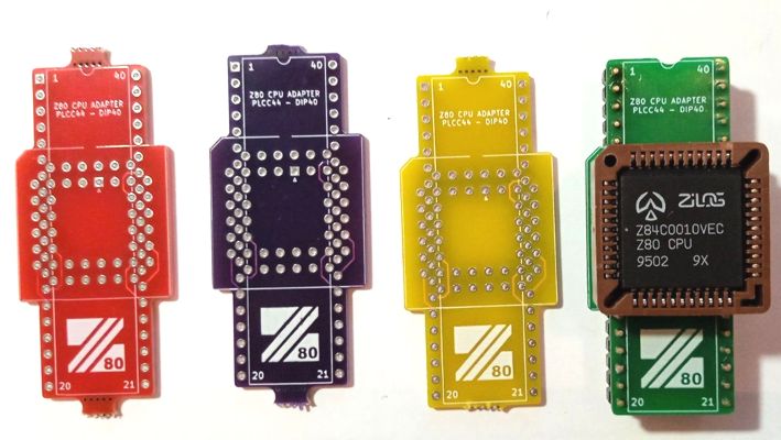
PCB Colour: Blue colour solder mask, white silk screen lettering
Surface Finish: Lead free HASL-RoHS
External size: 24 x 52 mm
Board Thickness: standard 1.6mm
Board Connector LQFP-44_10x10mm_P0.8mm, 2.54mm:PinHeader_1x20_P2.54mm_Vertical_SMD_Pin1Left
Copper Thickness: 35um
Card weight: 3g
Bill of materials
BOM amount for 1 depanelized adaptor:
| Identifier | Value | Qty | Notes | |
|---|---|---|---|---|
| Printed Circuit Board | 24 x 52 mm Z80 PLCC44 to DIP40 Adaptor | 1 | v1.20 | |
| Socket | IC 1 | PLCC, 44 pins, through hole | 1 | Mouser No: 649-54020-44030LF Digi-Key Part Number: 2057-PLCC-44-AT-ND Solder to top side of PCB |
| Connector | J1,J2 | 2.54mm Pin header, Vertical, 1x20 SMD machined | 2 | Connector_PinHeader_2.54mm:PinHeader_1x20_P2.54mm_Vertical_SMD_Pin1Left Solder to bottom side of PCB |
| Capacitor | C1 | 100n 0805 Unpolarized ceramic capacitor | 1 | Capacitor_SMD:C_0805_2012Metric_Pad1.18x1.45mm_HandSolder Solder to bottom side of PCB |
Assembly instructions and notes
■ Gerber files contain " JLCJLCJLCJLC" to the silk layer. You can specify a location of the order number, select the "Specify a location" option when you place an order. Only if you order via JLCPCB
■ Use a temperature-controlled soldering station and quality solder, use plenty of flux. Take care not to leave solder bridges as any short circuit will most likely lead to failures
■ Use a temperature-controlled heat gun station and quality solder paste, use plenty of flux. Take care not to leave solder bridges as any short circuit will most likely lead to failures
■ Assembly:
1 - First start with pin headers: Insert and solder 2x Pin header, Vertical, 1x20 THT to bottom side of PCB. Pin headers are in 600mil pitch spacing. Use quality MACHINED golden plated pin headers, they are cheap and will protect your precious DIP socket.
2 - Turn around and insert Z80 and solder CPU PLCC-44 socket to top side of panelized PCB. Socket will need to be lifted a little bit as pin headers protruding to top of PCB about 0.5mm
3 - Remove outer cornners of panelized PCB from panel by snapping mouse bites (please don't use teeth this might end up in disaster and you with new dentures).
4 - Liberate single adapter and Enjoy!
Schematic
| File type | File name | File size | Last modified |
|---|---|---|---|
| Z80 CPU PLCC44 to DIP40 adapter Schematic v1.20 | 53 kB | 07/09/2025 | |
| Z8400 CPU Product specification, document PS017801-0602, Fig2,2a,2b | 1124 kB | 20/07/2021 | |
| Z80 CPU PLCC44 to DIP40 adapter Schematic v1.0 | 98 kB | 21/07/2021 |
Design Files
| File type | File name | File size | Last modified |
|---|---|---|---|
| PCB layers v1.20 | 102 kB | 07/09/2025 | |
| Gerbers 24 x 52 mm, 2 Layer FR4, v1.20 | 27 kB | 07/09/2025 | |
| DFM Analysis report JLCDFM, v1.20 | 2761 kB | 07/09/2025 | |
| PCB statistics report, v1.20 | 1 kB | 07/09/2025 | |
| PCB layers |
107 kB | 14/09/2021 | |
| Gerbers Panelized 1 row, 3 collumns 68 x 99 mm, 2 Layer FR4, |
111 kB | 14/09/2021 | |
| Solder paste stencil | Not available for this project | - | - |
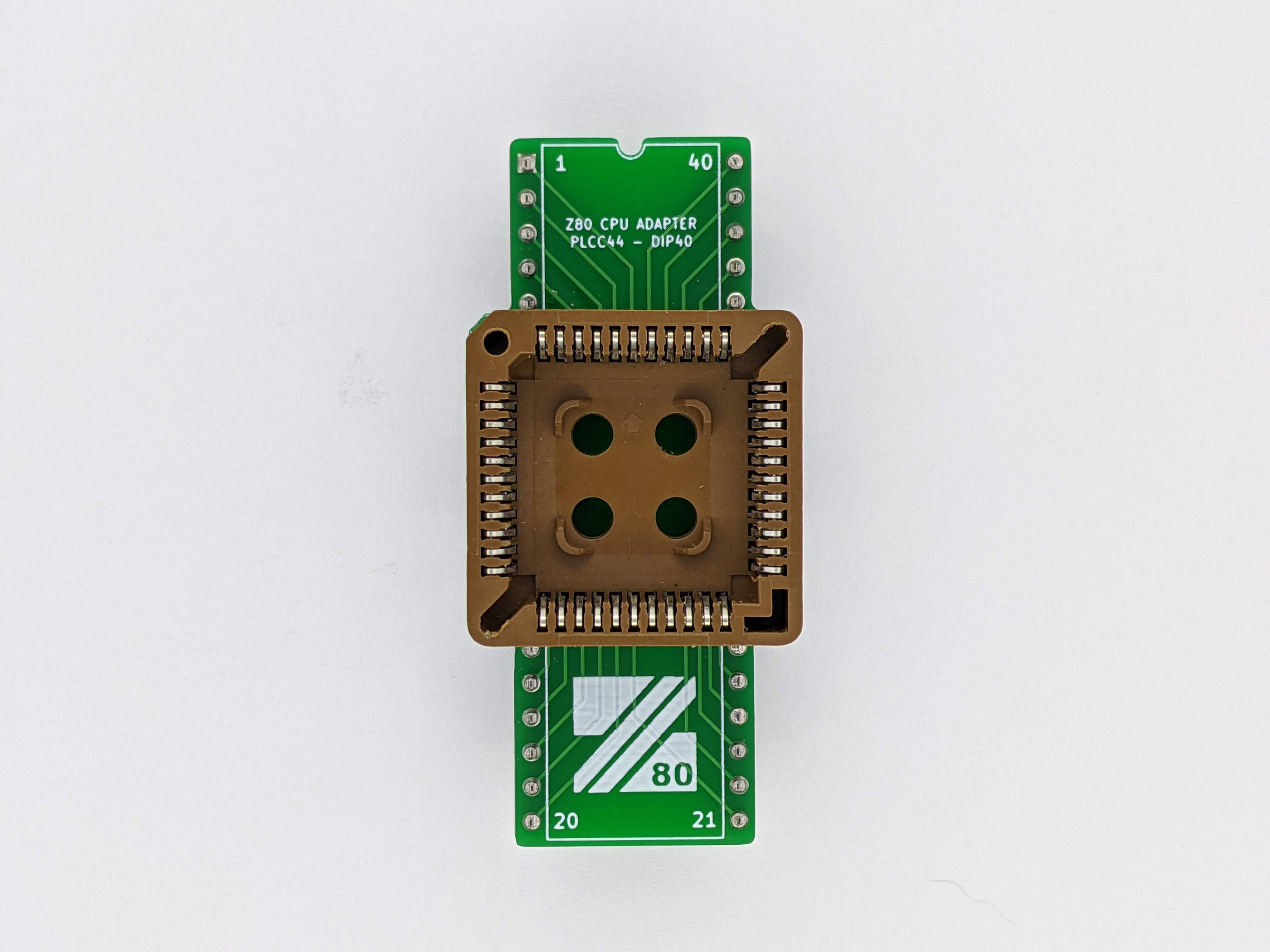
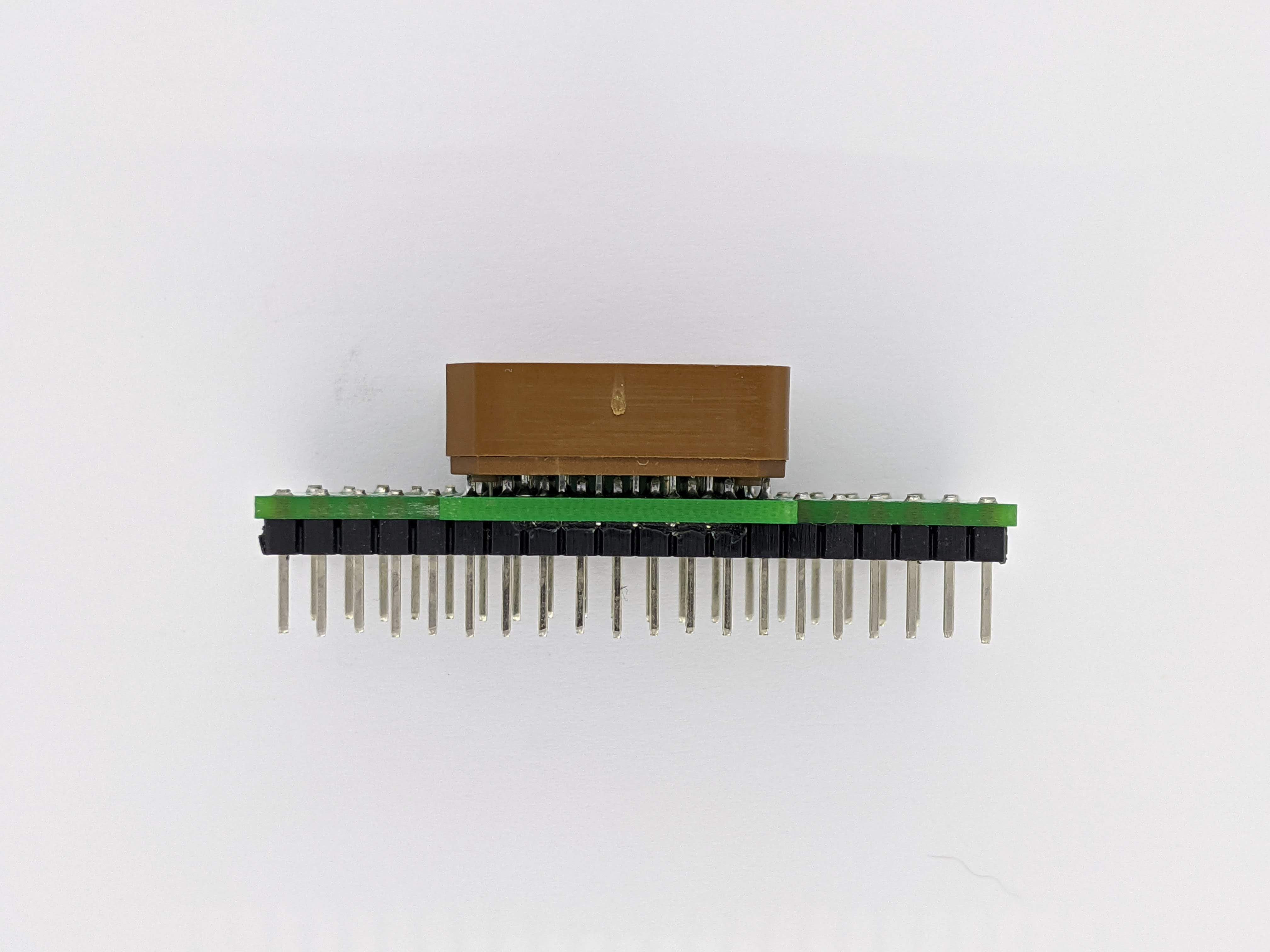
Photographs
click on pictures to enlarge
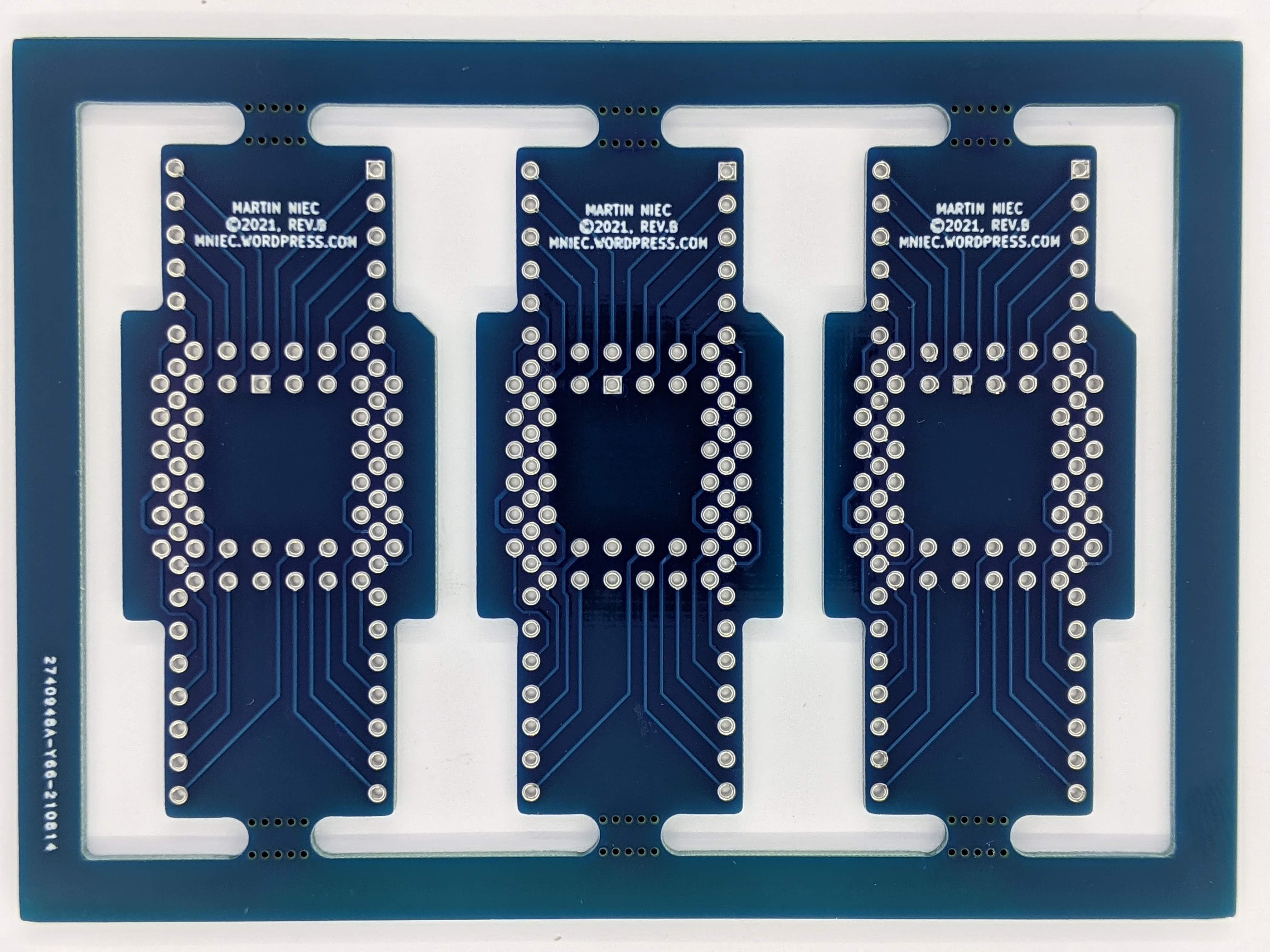
gerber files and photographs may vary, v1.1 (rev.1) pictured
gerber files and photographs may vary, v1.0 (rev.0) pictured

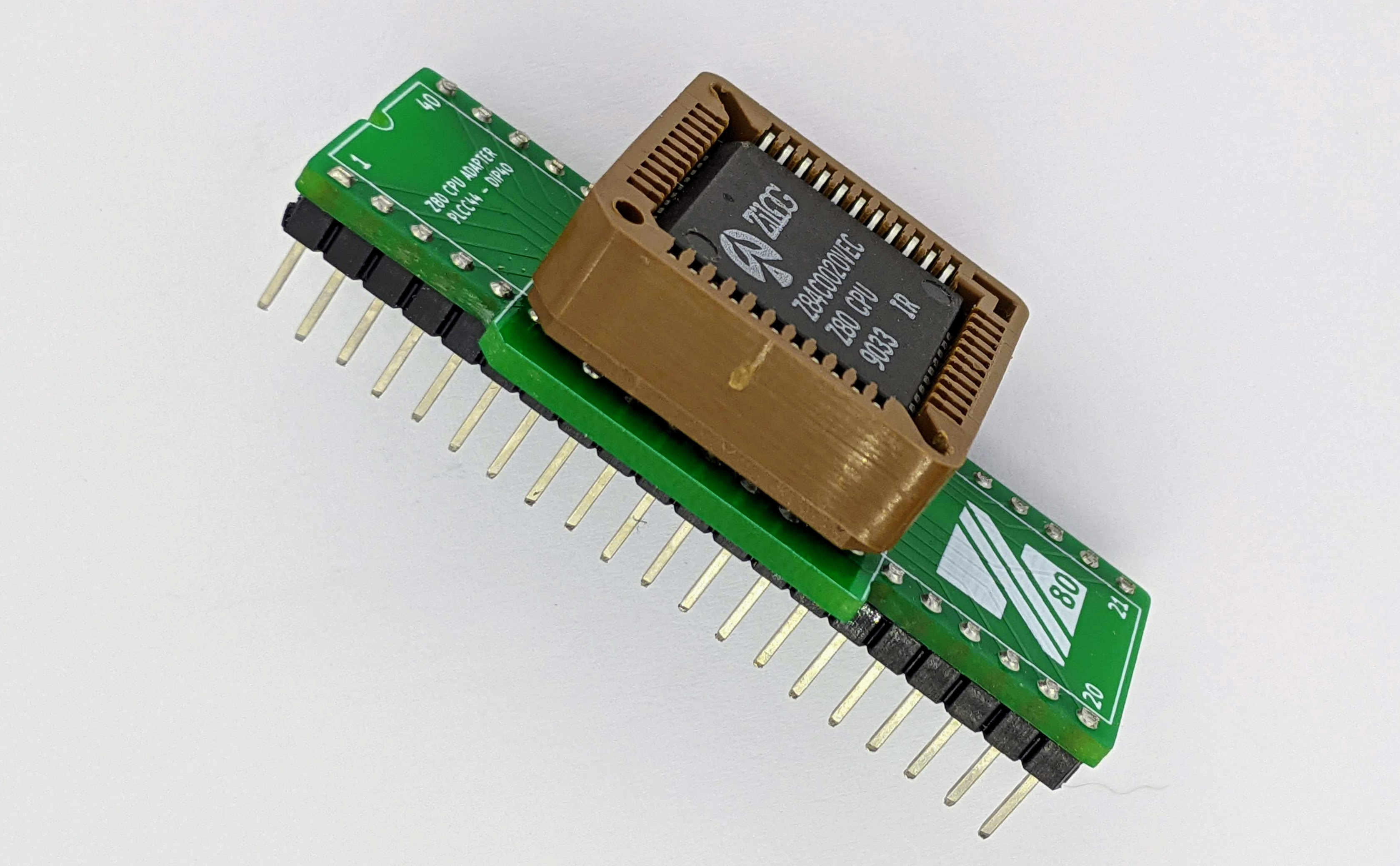


Z84C0006VEC tested up to 10MHz without any errors Photograph by Г. Саратов (G. Saratov)
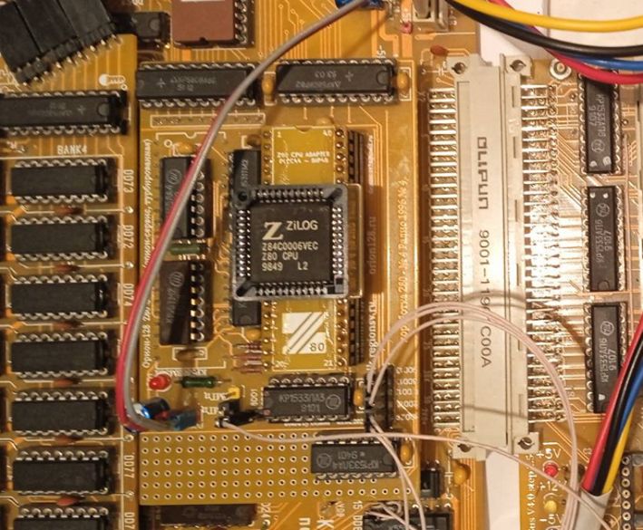

Processors tested at frequencies of 6, 10, 20 MHz Z84C0006VEC, Z84C0010VEC, Z84C0020VEC Photograph by Г. Саратов (G. Saratov)
Versions and revisions
This section lists the project version and revision history.
v1.20
■ Various silkscreen updates
■ Various PCB updates - thicker traces, added copper fills
■ Added bypas capacitor
■ Various updates for better DFM and panelization
■ Various visual updates
v1.1
■ Various silkscreen updates
■ Various cosmetic updates
■ Traces update
■ panelized PCB in 3x1 grid
v1.0
■ prototype