Marten Electric 電気テン @ Home
Vintage audio gear connoisseur, computer enthusiast, time nut, music lover, vintage games gamer, nerd, tinkerer and shady electronic projects makerEurocard DIN41612 3U riser extender PCB card 220mm with test points and PCB guide
Introduction
I have originally designed this riaser card for few of my projects, but this turn out so well that I have now posted all schematic, gerber files and documentation to fellow enthusiast such as yourself :) Perhaps (and I hope) content in this obscured corner of interwebs will inspire you to start your own projects.
Eurocards system in general is enormously versatile for all kinds of projects thanks to standardized mechanical dimensions and quality connectors. You can literally make any project and skale it up as much as you wish. For example this extender card can be used as exnteder card as the name suggest doh..., but also to intercept and trouble shoot signals and as a prototyping platform if you attach solderless breadboard to it.
You can use these cards in industry standard DIN subrack or Eurorack.
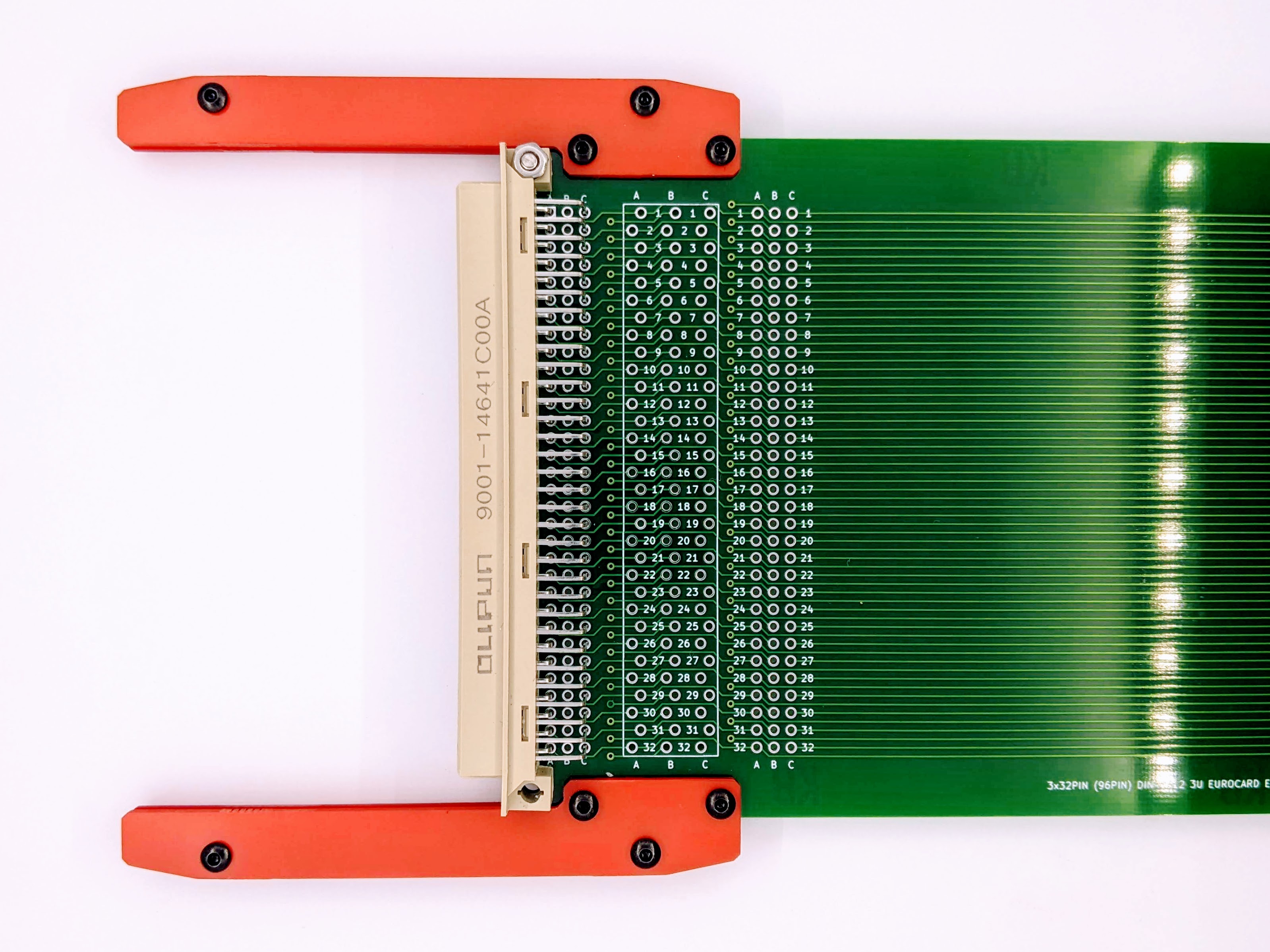
Card will fit nicely in PCB guide rails. Card also contains 3x32pin rows for test points and 3x32pin rows for 0.1" Dupont header connectors.
Card has been designed to be very versatile and you can fit 96 and 64 pin DIN connectors each side if you wish or 64pin female edge connector.
Quite recently I have figured out, that card can also be used for prototyping if you don't install red PCB rais and fit female header in test point area. Stick breadboard directly on card and voala :)
These boards look absolutely gorgeous in standard green solder mask if you going for that standard industrial look. I can advise you where to buy connectors, however you can use any standard 96/64pin DIN Eurocard connectors or 2x32, 64pin PCB edge connectors.
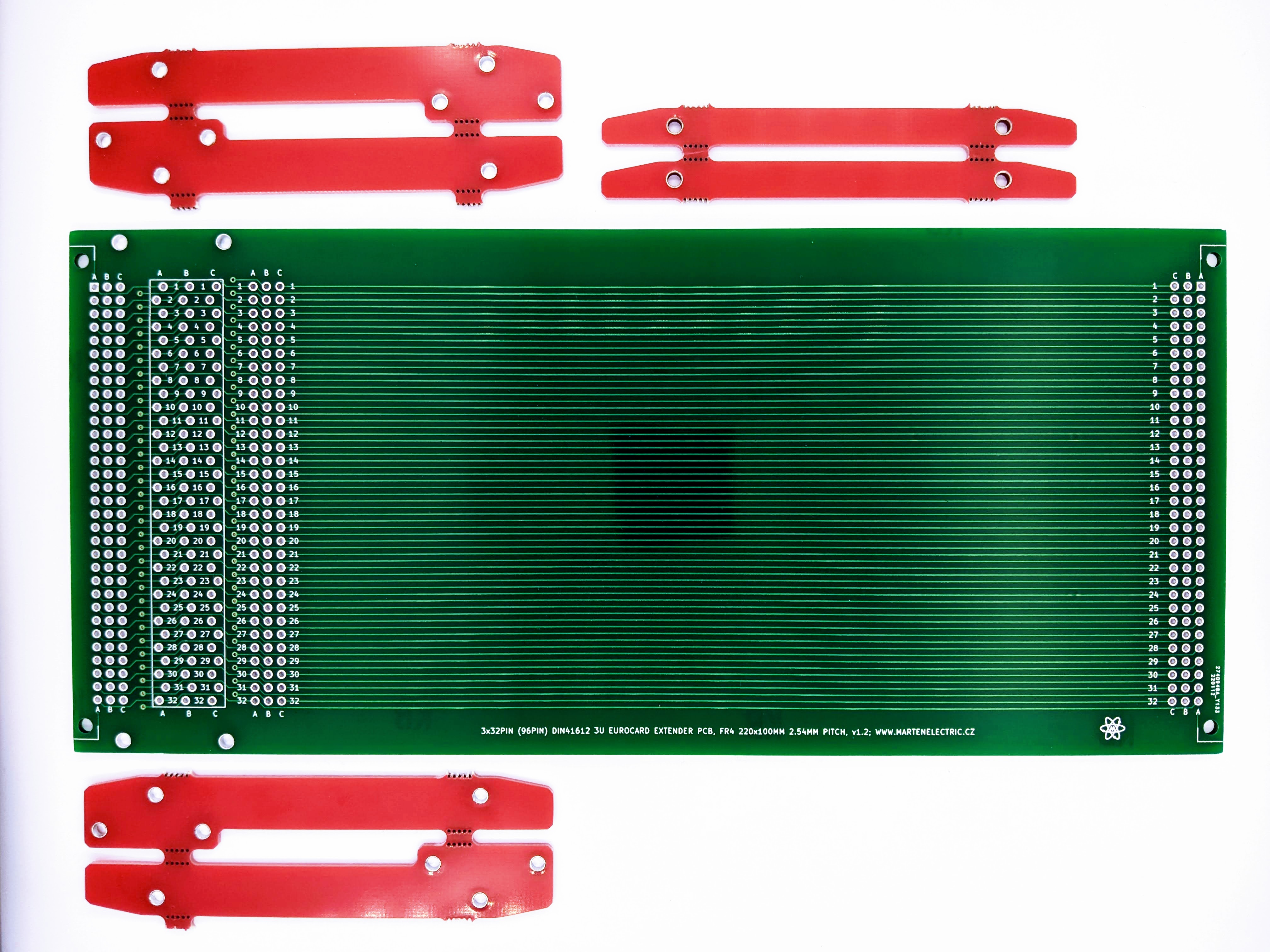
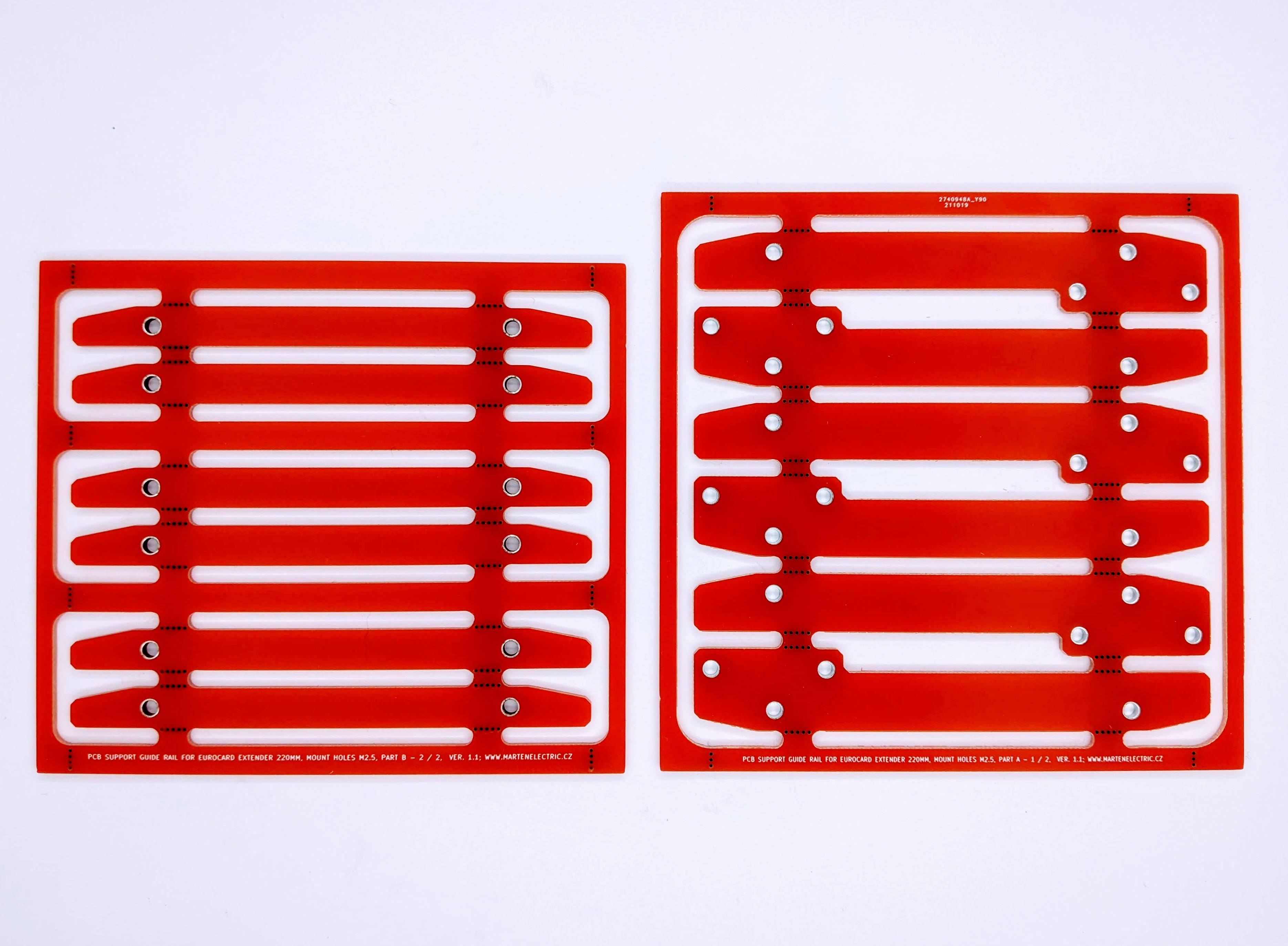
PCB support guide rails for extender card look best in RED colour (Violet color would also be nice). You have to assemble them yourself.
⊂(◉‿◉)つ
Except where otherwise noted, content on this site is licensed under a Creative Commons Attribution 4.0 International license. CC-BY-4.0
I have created content on this website free to use for personal, educational and commercial purposes. If you like or use my work, please mention me or perhaps consider a donation.
| or |
... but if you feel like getting something for nothing isn't your cup of tea (completely understandable) (ಥ﹏ಥ) and a prefer to support me and get something back in return, then you can purchase directly on my eBay or Tindie shop. However if you are still up for an adventure */in very positive way/* (and are happy to have PCB's made yourself in your favourite PCB house - PCBWay is highly recommended), then carry on, download gerber files and have fun! ( ͡° ͜ʖ ͡°)


EDA preview
click on pictures to enlarge

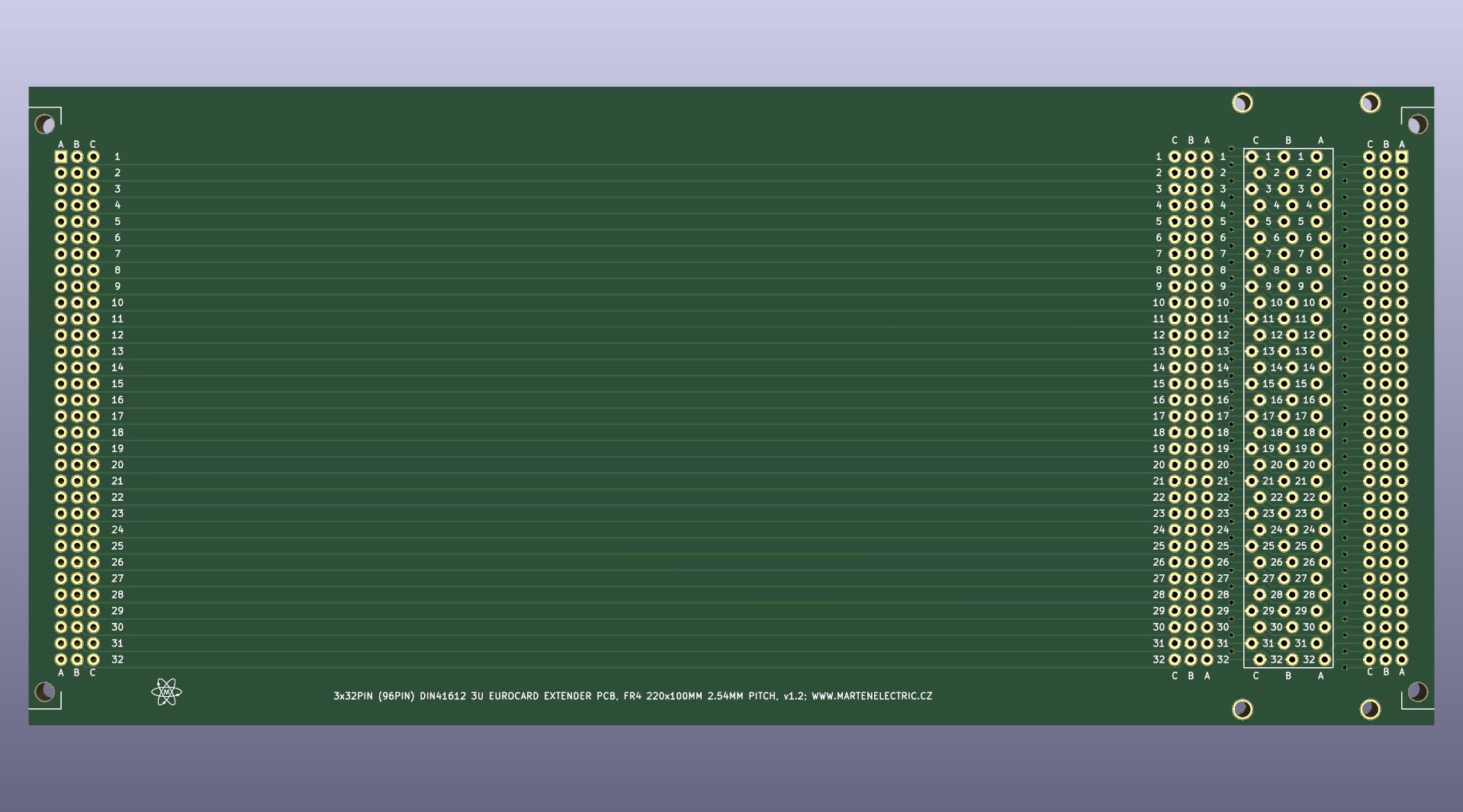
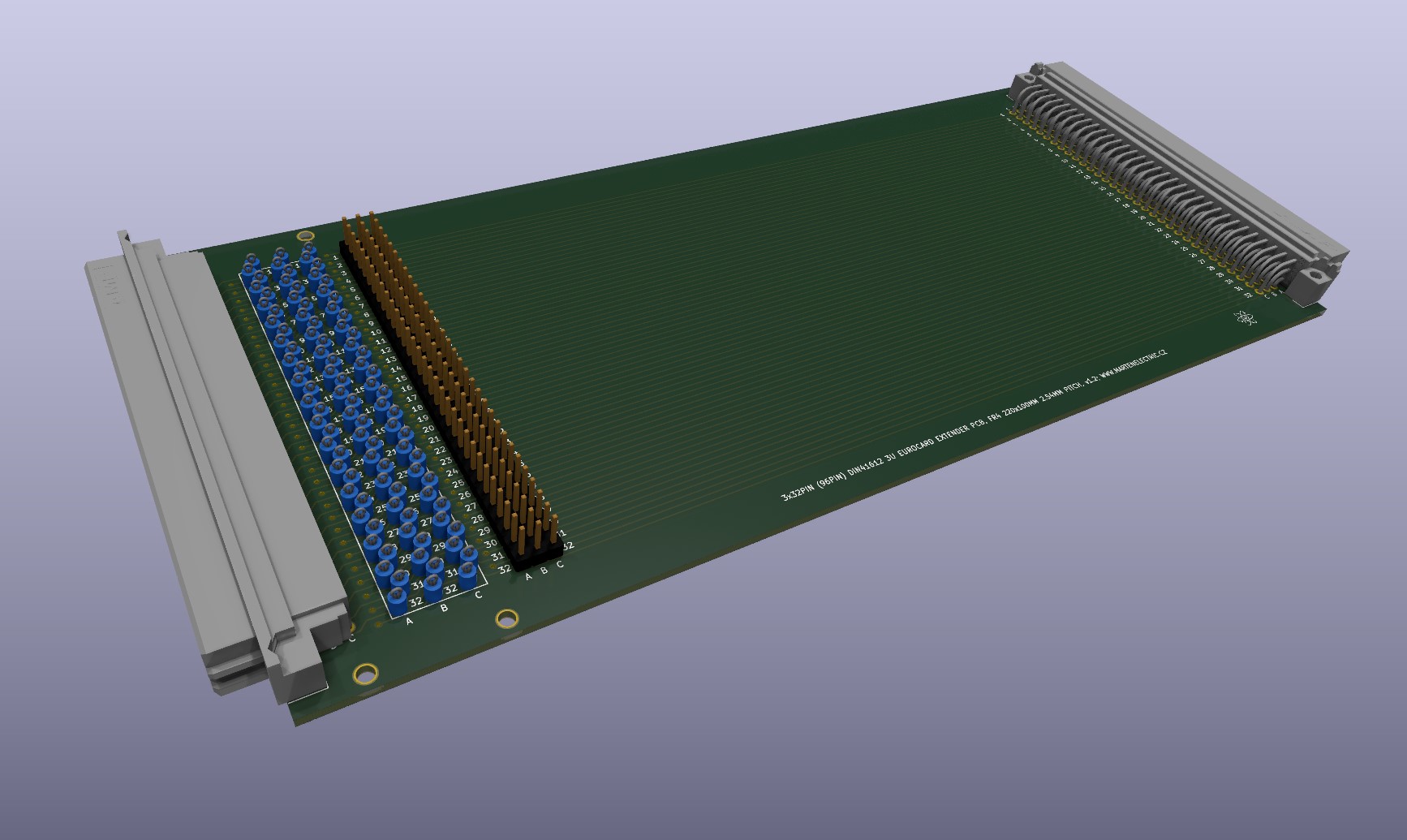
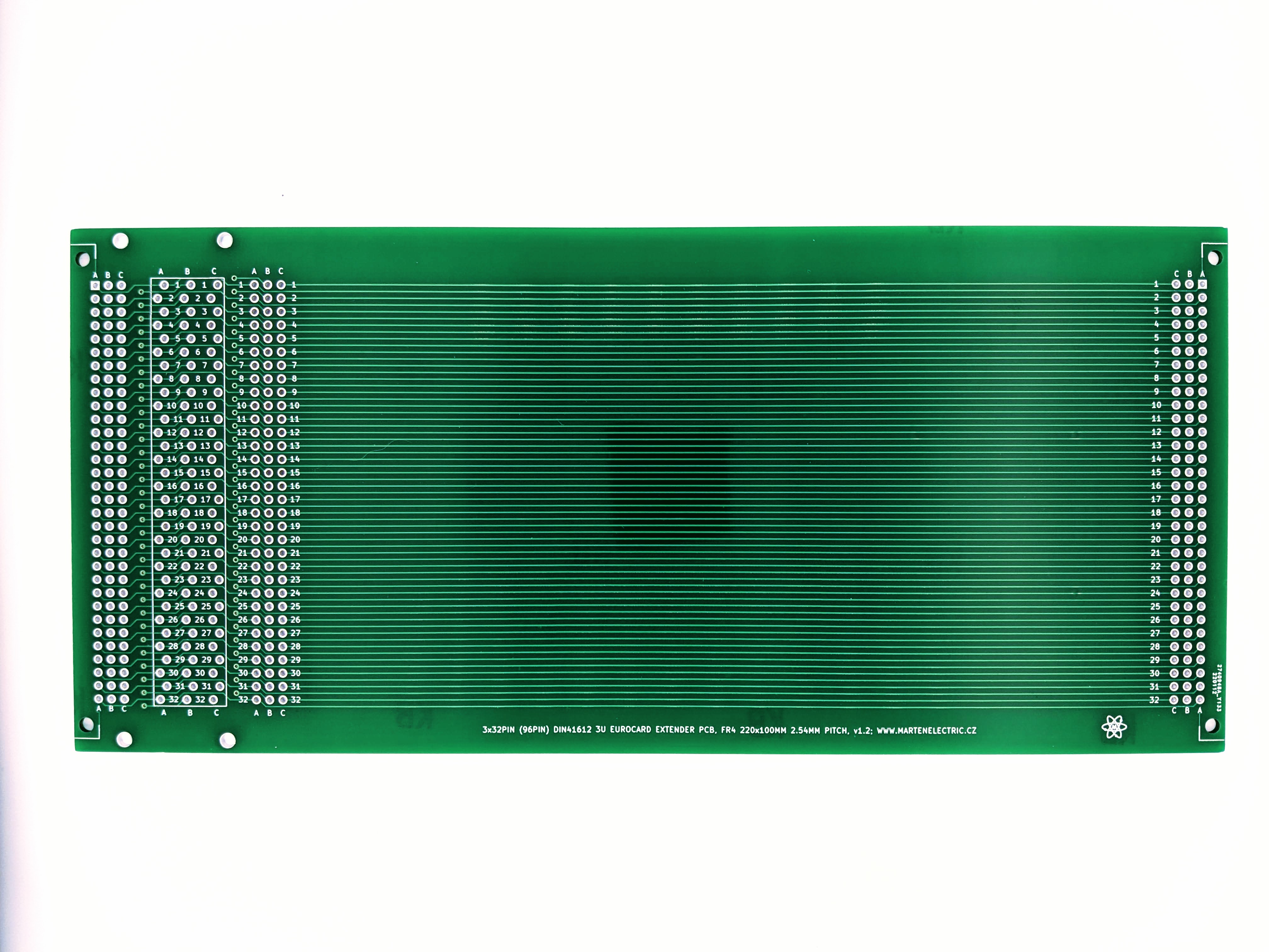
3D render v1.2
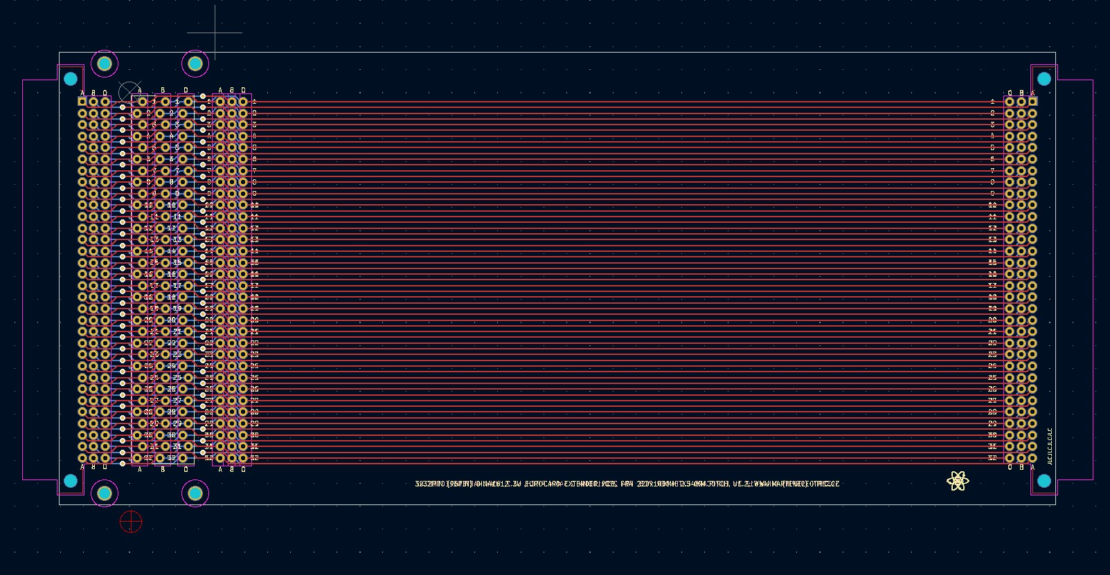
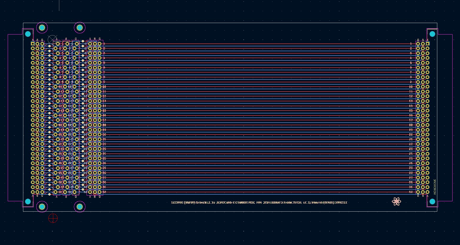
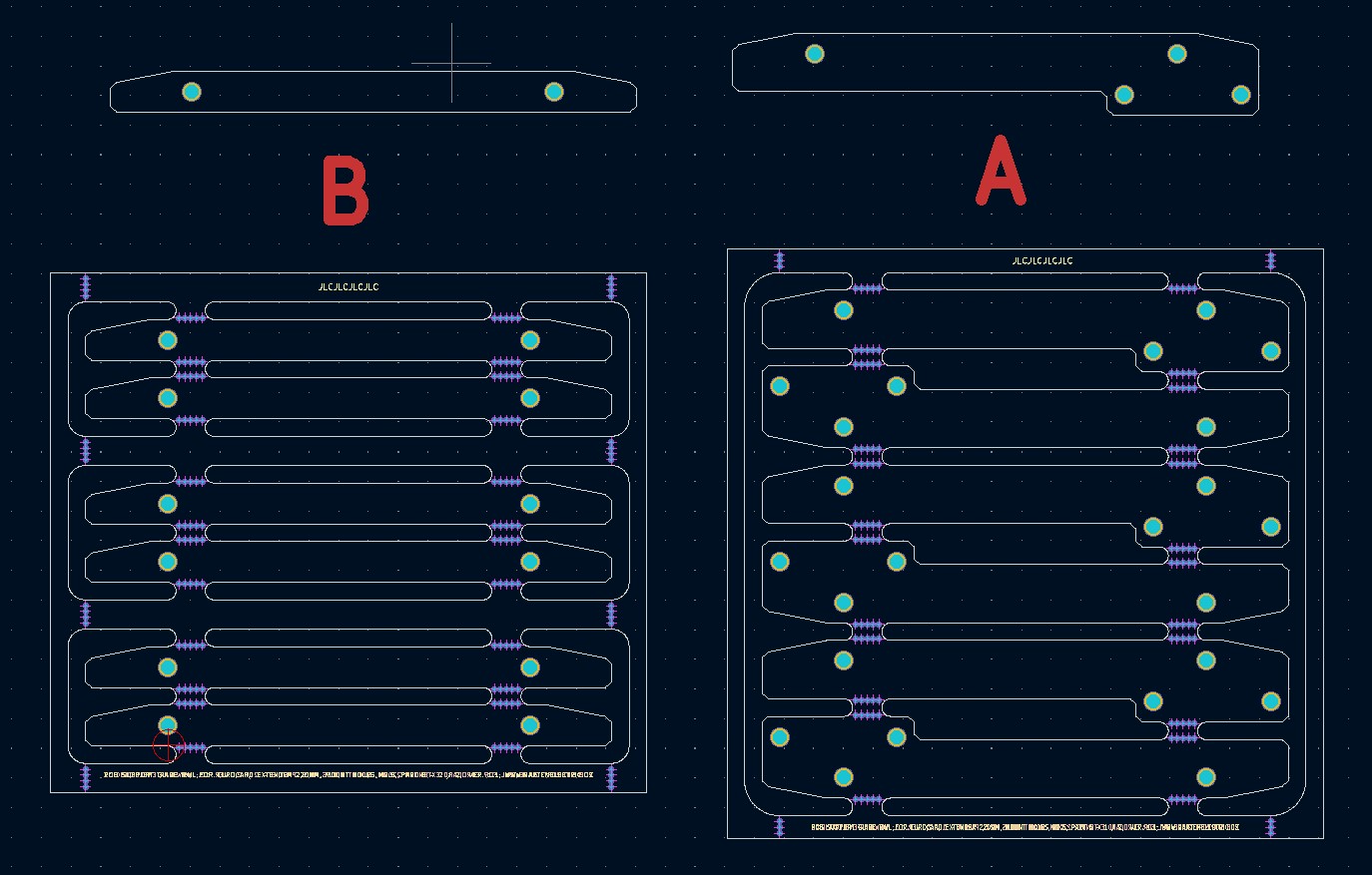
PCB design layout
Specs
Extender card
Board Type: Extender / riser card
Board Material: FR4-Standard Tg 130-140C Epoxy Glass Composite
Layers: Double sided
PCB Colour: Green colour solder mask, white silk screen lettering
Surface Finish: Lead free HASL-RoHS
External size: 220x100mm
Board Thickness: standard 1.6mm fits in standard guide rail and standard Eurocard front panel
Pitch: 2.54mm (100.00 mils)
Hole matrix: 2 x 96 holes for DIN connector (192 holes in total), 2x 96 holes 1.00mm for test points and Dupont connectors
Hole size: 1.00mm
Mounting holes: Standard pitch DIN 41612. 4x mounting holes 2.50mm
Board Connector / Footprint: DIN 41612 2x32pin or 3x32pin 64 / 96 Pin connector, you can also fit 64pin female edge connector.
Copper Thickness: 35um
Card weight: 100g
PCB support guide rails
Board Type: Extender / riser card
Board Material: FR4-Standard Tg 130-140C Epoxy Glass Composite
Layers: Double sided
PCB Colour: Red solder mask
Surface Finish: Lead free HASL-RoHS
Mounting holes: 2x mounting holes 2.50mm
External size: 100x100mm, assembled approx. 90 x 14mm x 5mm
Board Thickness: 1.60mm
Card weight: 50g
Bill of materials
The following list contains the parts that are required to assemble this card.
| Identifier | Value | Qty | Notes |
|---|---|---|---|
| Printed Circuit Board | 220mm DIN41612 3U riser card | 1 | v1.2 |
| Printed Circuit Board | Rail A panelized | 1 | v1.1 |
| Printed Circuit Board | Rail B panelized | 1 | v1.1 |
| Hardware | M2.5 x 8 mm screw | 8 | PCB rails |
| Hardware | M2.5 x 10 mm screw | 4 | DIN connector |
| Hardware | M2.5 nut | 12 | |
| Printed Circuit Board | 220mm DIN41612 3U riser card | 1 | v1.2 |
| Connector | Female DIN 41612 96pin 3x32pin right angle connector | 1 | |
| Connector | Male DIN 41612 96pin 3x32pin right angle connector | 1 | |
| Connector | 32pin dupont header 2.54mm pitch | 3 | |
| PCB Test points | 0.1" ceramic test points | 96 | William Hughes |
| Breadboard | 800 point solderless breadboard | 2 | Alternative use |
| Connector | Female DIN 41612 64pin 2x32pin right angle connector | 1 | 2nd alternative use |
| Connector | Male DIN 41612 64pin 2x32pin right angle connector | 1 | 2nd alternative use |
| Connector | 2x32pin 64pin PCB edge right angle connector 0.1" pitch | 2 | 3rd alternative use |
Assembly instructions and notes
■ Gerber files contain " JLCJLCJLCJLC" to silk layer. You can specify a location of the order number, select the "Specify a location" option when you place an order. Only if you order via JLCPCB
.
■ Fit Female and Male DIN 41612 96pin 3x32pin right angle connector or alternatives you wish to use
■ Use M2.5 screws and nuts to hold DIN connectors in place, thse don't need to be fitted to achieve strong mechanical connection however
■ Use a temperature-controlled soldering station and quality solder. Take care not to leave solder bridges as any short circuit will most likely lead to failures
■ To assemble rails: You have two big side PCBs and one middle as sandwich. All you have to do is to cut them out, smooth out mouse bite edges with sand paper and then bolt using M2.5 - M3.0 screws and nuts (or equivalent values in Imperial) or glue them together. You can buy test points on eBay (search for William Hughes PCB test points). Pictures are pretty much self explanatory, but please let me know if you need help with it.
■ Fit 2x 800 point solderless breadboards if you wish to use cards for prototyping
Schematic
| File type | File name | File size | Last modified |
|---|---|---|---|
| Not available for this project. | - | - | - |
Design Files
| File type | File name | File size | Last modified |
|---|---|---|---|
| PCB layers v1.2 | 171 kB | 03/01/2022 | |
| Gerbers 220 x 100 mm, 2 Layer FR4; v1.2 | 114 kB | 03/01/2022 | |
| PCB rail layers v1.1 | 150 kB | 03/01/2022 | |
| Gerbers rail A 100 x 100 mm, 2 Layer FR4; v1.1 | 15 kB | 17/10/2021 | |
| Gerbers rail B 102 x 89 mm, 2 Layer FR4; v1.1 | 16 kB | 17/10/2021 | |
| Solder paste stencil | Not available for this project | - | - |
Photographs
click on pictures to enlarge
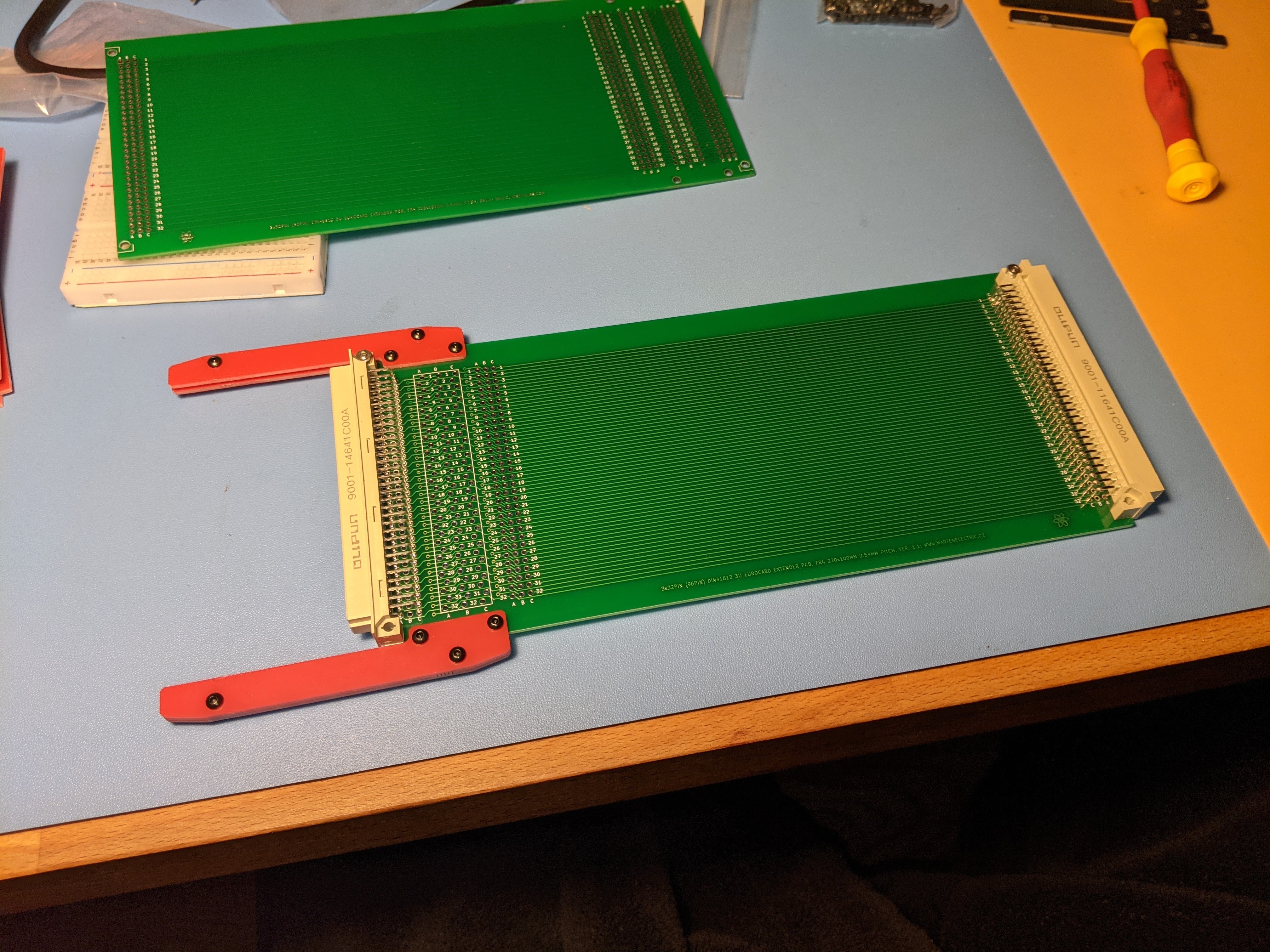
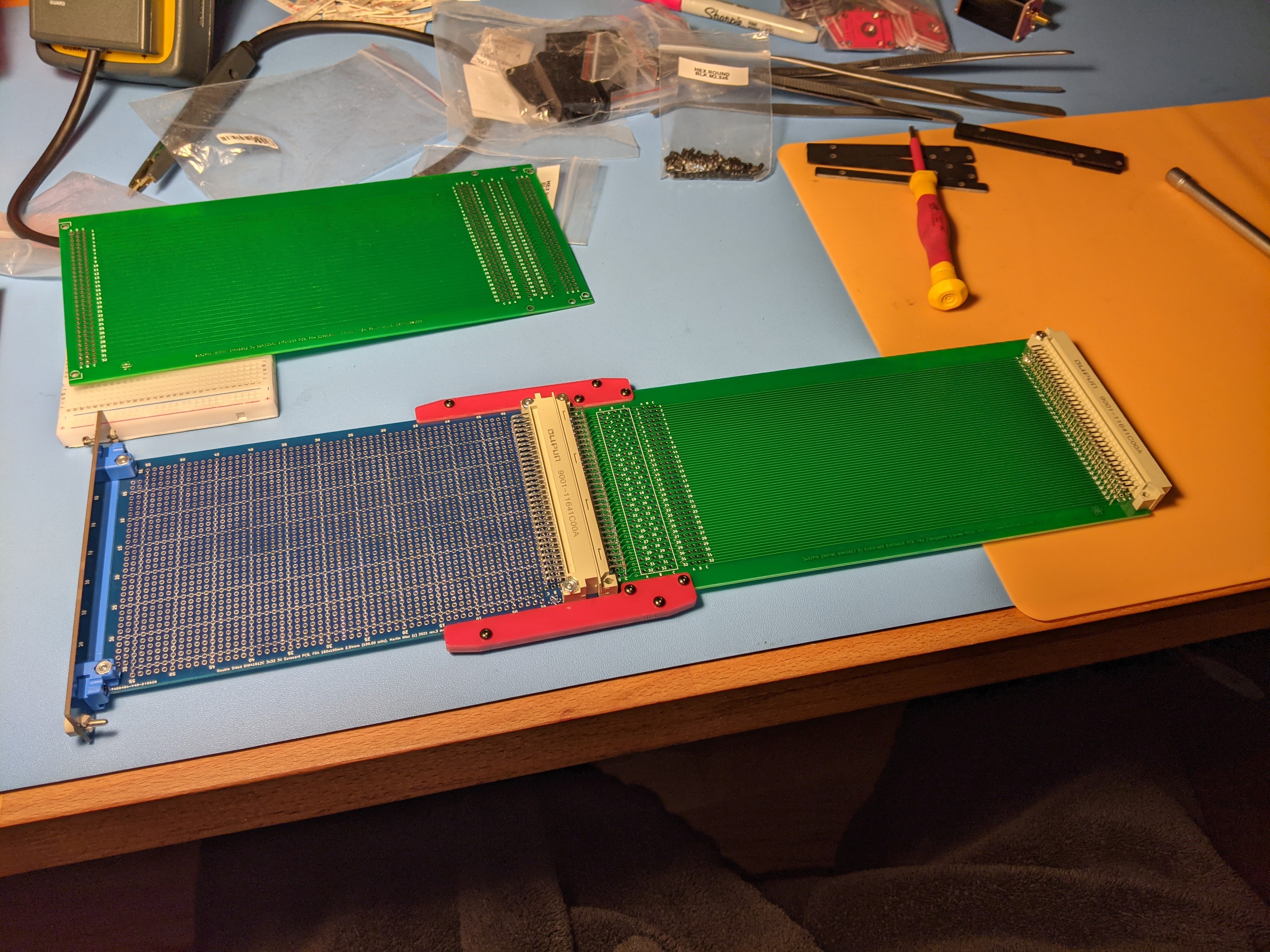
extender card can also accomodate two standard size 800pin breadboards

side rails come in red color solder mask
Versions and revisions
This section lists the project version and revision history.
Riser PCB 220mm v1.2
■ Holes for PCB test points made smaller to 1.00mm diameter.
■ Holes for PCB test points made ammended in zig-zag pattern, so that bigger PCB test points fit on PCB.
■ Mounting holes for red PCB rails made to exact measuremnt so that rails have perfect fit with no movement.
■ Various cosmetic updates
■ Various silkscreen updates.
PCB rails PCB v1.1
■ Mounting holes for red PCB rails made to exact measuremnt 2.50mm so that rails have perfect fit with no movement.
■ Adjusted shape to resemble Shroff