Marten Electric 電気テン @ Home
Vintage audio gear connoisseur, computer enthusiast, time nut, music lover, vintage games gamer, nerd, tinkerer and shady electronic projects makerMicrobus Passive Backplane PCB for Eurocards DIN41612 4 slot 3U 16HP
Introduction
I have originally designed this backplane for a few of my projects (Rubidium frequency standard and Z80 Micro Computer), but this turn out so well that I have now posted all schematic, gerber files and documentation to fellow enthusiast such as yourself :) Perhaps (and I hope) content in this obscured corner of interwebs will inspire you to start your own projects.
Eurocard is a European standard format for printed circuit board (PCB) cards that can be plugged together into a ![]() standard chassis sub-rack which, in turn, can be mounted in a 19-inch rack. The chassis consists of a series of slotted card guides on the top and bottom, into which the cards are slid so they stand on end, like books on a shelf. At the spine of each card is one or more connectors which plug into mating connectors on a backplane that closes the rear of the chassis.
standard chassis sub-rack which, in turn, can be mounted in a 19-inch rack. The chassis consists of a series of slotted card guides on the top and bottom, into which the cards are slid so they stand on end, like books on a shelf. At the spine of each card is one or more connectors which plug into mating connectors on a backplane that closes the rear of the chassis.
Eurocards system in general is enormously versatile and convenient way to create any kind of project where high functionality, reliability and ruggedness are required. System uses standardized mechanical dimensions and quality connectors. Eurocards PCB's come in many sizes (wikipedia article). This is single height most common size 3U single height card. I have also designed other 3U passive backplanes if you require different size tailored to your project. More about Microbus (wikipedia article).
Design of my backplane PCB was inspired by ECB Backplane 4 from RetroBrew Computers Wiki. I definitely recommend going through their webpage!
Design overview
Ideally you will use backplane free standing on table, however design facilitates PCB fit in industry standard 3U subrack, however Z rais is required to install in 3U subrack. Backplane was designed according to standard mechanical values, therefore connectors' mechanical positions will match perfectly with PCB guide rails rails with the front panel Eurorack should you decide to use this solution. Standardized card size is 3U height with 4 slots for 4HP cards (16HP 3U) and will fit into a half width 19" 40TE 3HE standardized subrack. I'm using this with standard 160mm depth cards, but you can use whatever fits in your rack (100,160,240mm).
Main design features:
Backplane PCB has been designed to be very flexible and can be used with large variety of industry standard power and signal connections:
■ Signal traces - - (passive termination) are not terminated nor have determined pinouts apart from PWR and GND connectors allowing you to configure the backplane to exactly match the requirements of the system. Each pin is bussed across the board, allowing you using row B as GND guard rails thus minimizing crosstalk on rows A and C.
■ Power connectors - 2x 4pin power (Molex) connector with 5.08mm pitch and/or standard DC barrel jack 5.5mm / 2.1mm center pin positive. Footprint silkscreen on front and back side allowing molex connector to be fitted on both sides, should you decide to fit PCB in the subrack.
■ Two separate power rails and one single ground plane available. (Vcc, GND, GND, Vdd).
■ Supply voltages provided via dedicated power connectors facilities: - 4 pin Molex power connector 5.08mm pitch and/or standard DC barrel jack 5.5mm / 2.1mm center pin positive.
■ DPDT, DPST, SPST Switch footprint alows you to switch VDD and VCC power lines.
■ Footprint for R and LED power status VCC, VDD on board
■ Rack Z-mounting holes are NOT electrically connected
■ Capacitor footprint 7.62mm for the silky smooth DC line and outstanding high-frequency noise suppression
■ Footprint supports off the shelf standard DIN 41612C 96/64pin Eurocard connectors or 2x32, 64pin PCB edge connectors.
■ Multiple backplanes can be placed side by side with loss of slot space
Backplane can also be extended with 2 slot bridge connector card to create a daisy chain array of backplanes if required. You can literally make any kind of project and scale it up as much as you wish.
These boards look absolutely gorgeous in standard green solder mask if you go for that standard industrial look. I can advise you where to buy connectors. however you can use any standard off shelf connectors which you can pretty puch purchase anywhere.
⊂(◉‿◉)つ
Except where otherwise noted, content on this site is licensed under a Creative Commons Attribution 4.0 International license. CC-BY-4.0
I have created content on this website free to use for personal, educational and commercial purposes. If you like or use my work, please mention me or perhaps consider a donation.
| or |
... but if you feel like getting something for nothing isn't your cup of tea (completely understandable) (ಥ﹏ಥ) and a prefer to support me and get something back in return, then you can purchase directly on my eBay or Tindie shop. However if you are still up for an adventure */in very positive way/* (and are happy to have PCB's made yourself in your favourite PCB house - PCBWay is highly recommended), then carry on, download gerber files and have fun! ( ͡° ͜ʖ ͡°)


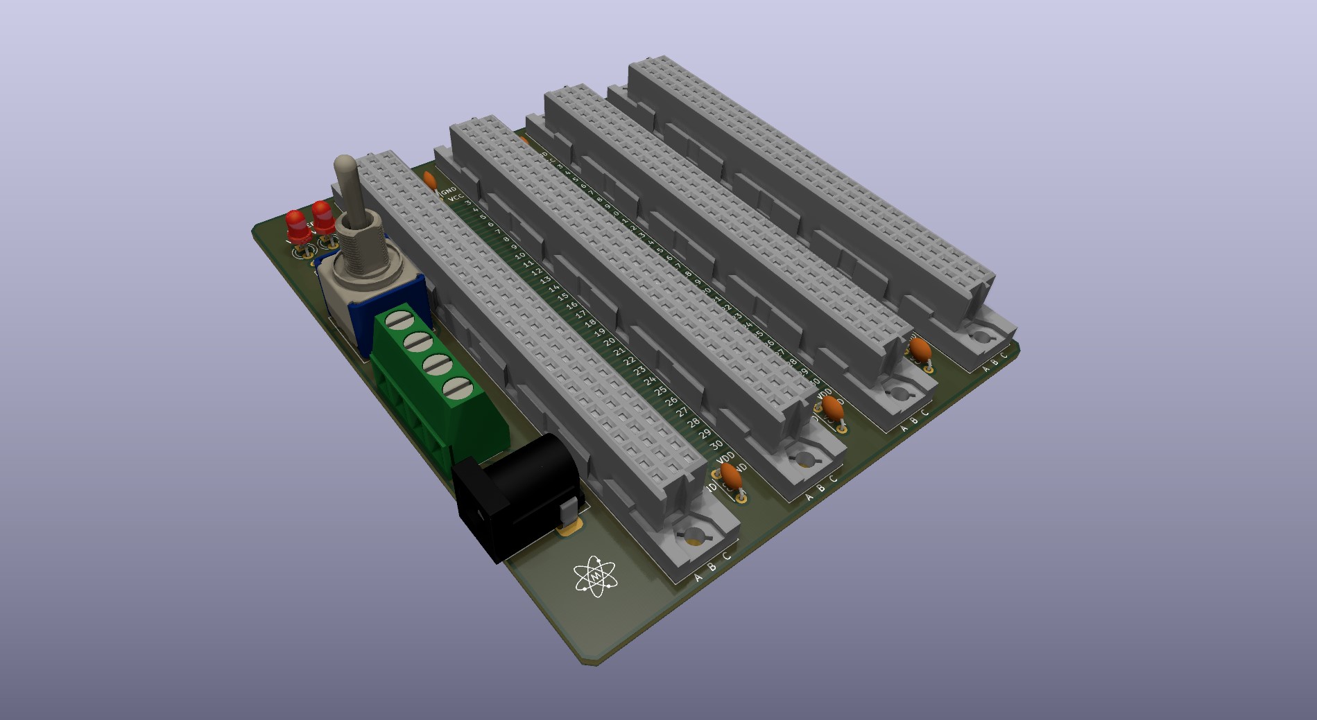
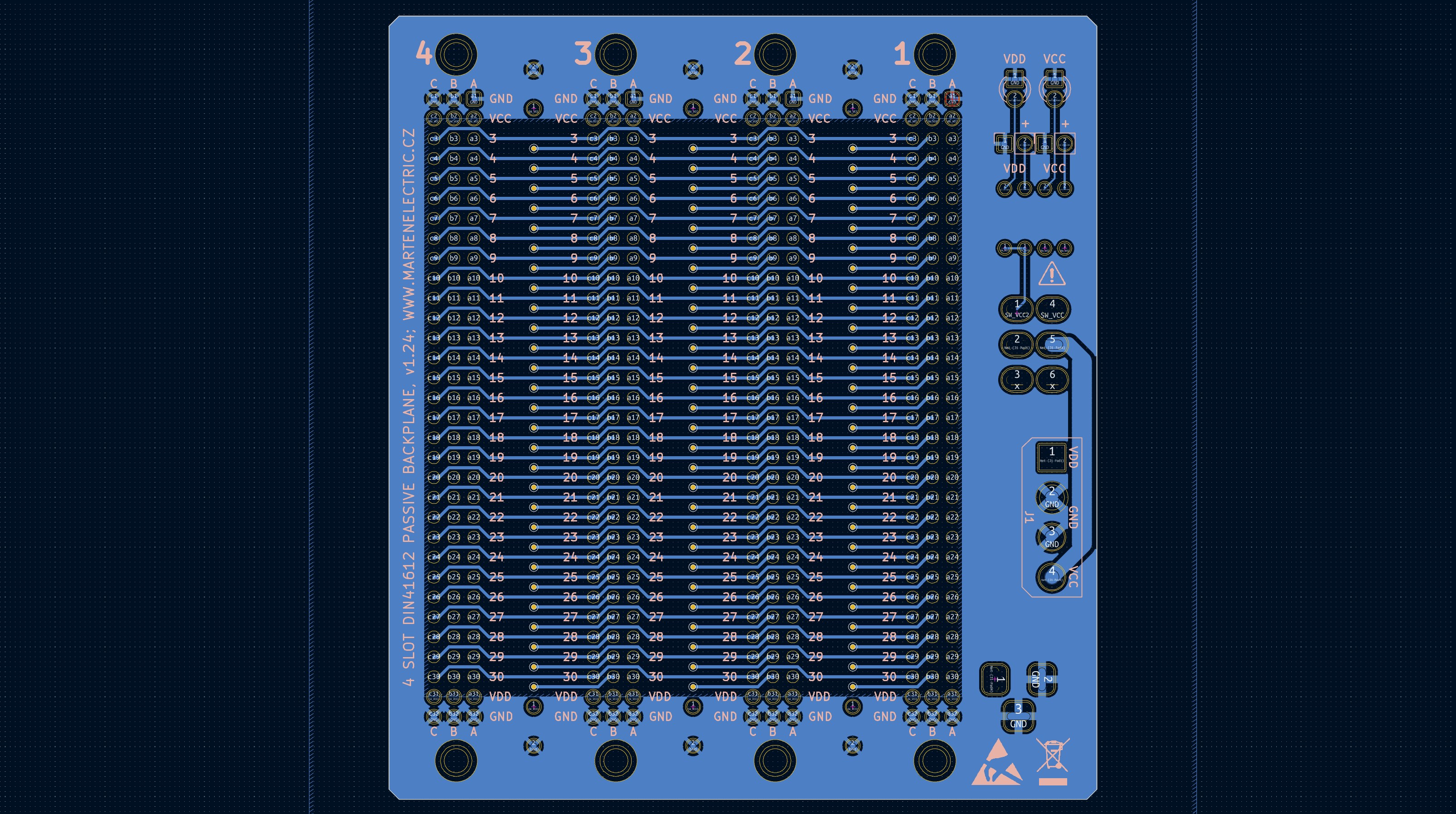
EDA preview
click on pictures to enlarge
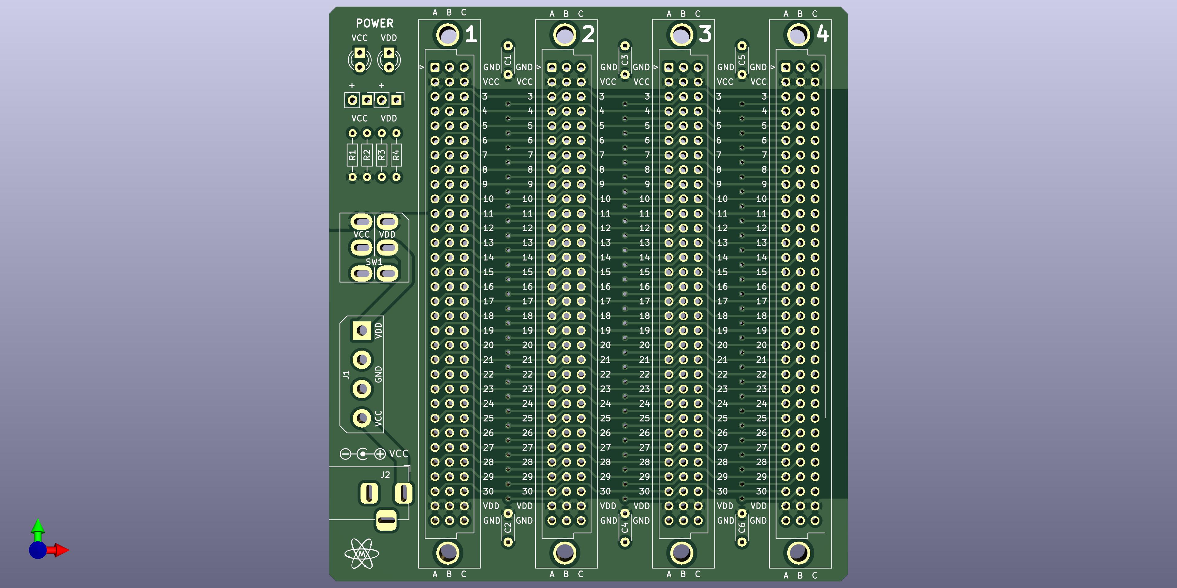
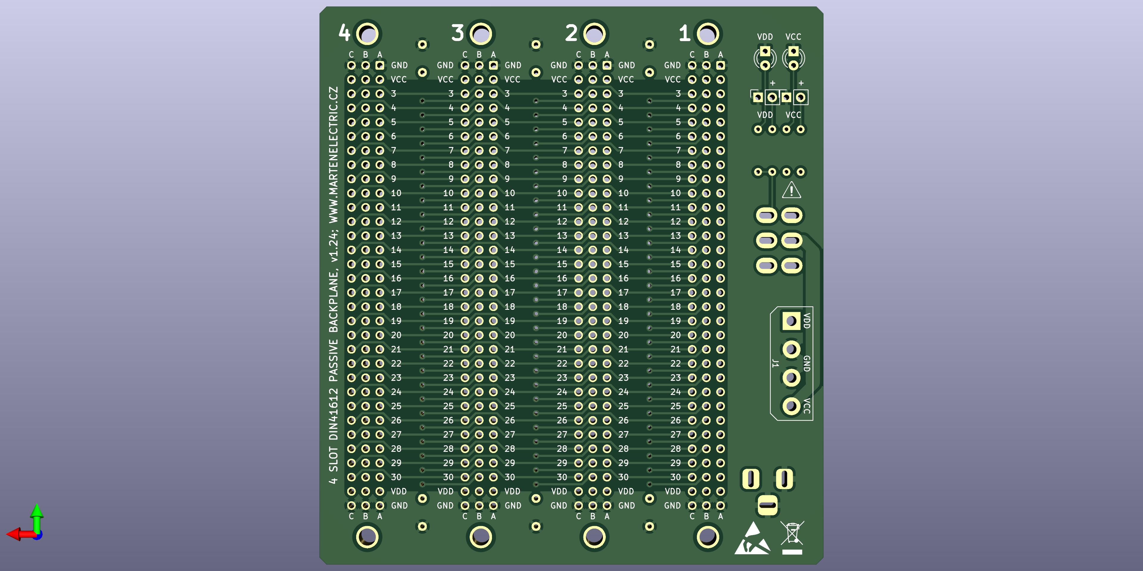
3d render v1.21
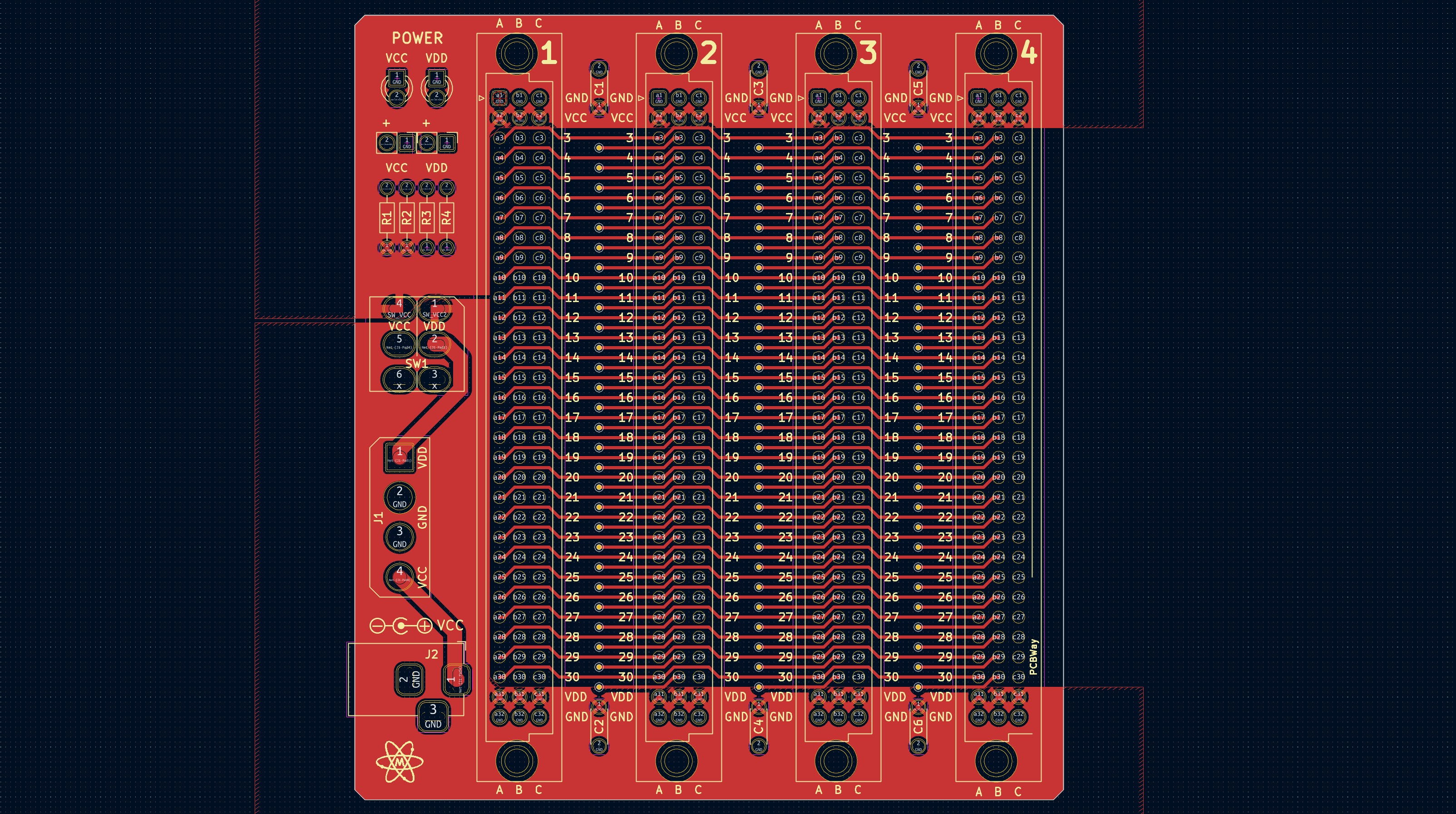
PCB design layout
Specifications
Board Type: Backplane
Board Material: FR4-Standard Tg 130-140C Epoxy Glass Composite
Layers: Double sided
PCB Colour: Green colour solder mask, white silk screen lettering
Surface Finish: Lead free HASL-RoHS
External size: 89 x 99 mm
Board Thickness: standard 1.6mm
Pitch: 2.54mm connectors (100.00 mils)
Connector hole matrix: 96 DIN 41612C compatible / PCB edge card connector 2x32 / 64pin compatible
Hole size: 1.00mm
Mounting holes: Standard pitch 3U subrack mount
Board Connector / Footprint: DIN 41612 4 slot x 96pin or 2x32pin 64 / 96 Pin connector, you can also fit 64pin edge connector in. Power connector is via one of the cards or use capacitor (C1-C6 as power connector). Card is double voltage ready. (Vcc, GND, GND, Vdd).
Copper Thickness: 35um
Card weight: 30g
Bill of materials
| Identifier | Value | Qty | Notes | |
|---|---|---|---|---|
| Printed Circuit Board | 75 x 99 mm 4 slot Microbus backplane | 1 | v1.1 | |
| Hardware | M2.5 x 10 mm screw | 8 | ||
| Hardware | M2.5 nut | 8 | ||
| Connector | E1-E4 | DIN41612 connector, type C, Vertical, 3 rows 32 pins wide | 4 | DIN41612_C_3x32_Female_Vertical_THT |
| Connector | E1-E4 | Female DIN 41612 64pin 2x32pin right angle connector | 4 | 2nd alternative use |
| Connector | E1-E4 | 2x32pin 64pin PCB edge right angle connector 0.1" pitch | 4 | 3rd alternative use |
| Power Connector | J1 | TerminalBlock:TerminalBlock_bornier-4_P5.08mm | 1 | Molex 5.08mm pitch 1x04 pin male connector |
| Power Connector | J2 | Connector_BarrelJack:BarrelJack_Horizontal | 1 | DC Barrel jack 5.5mm |
| Switch | SW1 | DPDT, DPST, SPST Switch up to 2x03pin 4.45mm pitch | 1 | |
| LED | LED1, LED2 | LED_THT:LED_D3.0mm | 2 | Resistor | R1, R2 | Resistor_THT:R_Axial_DIN0204_L3.6mm_D1.6mm_P7.62mm_Horizontal | 2 | 1k resistors, or calculate forward voltage |
| Capacitor | C1-C6 | C_Disc_D3.0mm_W1.6mm_P2.50mm | 6 | THT |
| Connector, power | C1, C2 | PinHeader_2.54mm:PinHeader_1x02_P2.54mm_Vertical | 2 | Use for or Dual V power input via backplane |
Assembly instructions and notes
■ Gerber files contain " WayWayWay" to the silk layer. You can specify a location of the order number, select the "Specify a location" option when you place an order. Only if you order via PCBWay.
■ If you will use PCB backplane as rack mount: - install molex connectors, resistors, LED's and pin headers to the back side, otherwise components won't fit due to Z rails.
■ If you will use PCB backplane as table top or custom mount: - install all components to front side. Use standoffs or rubber feet to electrically isolate from surface.
■ Use M2.5 screws and nuts to hold DIN connectors in place, these don't need to be fitted to achieve strong mechanical connection however
■ Use a temperature-controlled soldering station and quality solder. Take care not to leave solder bridges as any short circuit will most likely lead to failures
■ Use capacitor C1-C2 for silky smooth power lines.
■ Ground is common for both power rails, E1-E4 DIN connector holes are mechanical and are not connected to ground.
Schematic
| File type | File name | File size | Last modified |
|---|---|---|---|
| PCB schematic for 4 slot backplane v1.21 | 385 kB | 20/07/2022 | |
| PCB schematic for 4 slot backplane v1.21 | 613 kB | 20/07/2022 | |
| PCB schematic for 4 slot backplane v1.0 | 383 kB | 19/06/2021 | |
| Microbus backplane pinout (from v1.0) | 90 kB | 08/09/2025 | |
| Microbus backplane pinout (from v1.0) | 128 kB | 08/09/2025 |
Design Files
| File type | File name | File size | Last modified |
|---|---|---|---|
| Vero Eurocard bus systems - Microbus backplanes | 175 kB | 08/09/2025 | |
| PCB layers v1.1 | 191 kB | 20/01/2022 | |
| PCB layers v1.21 | 216 kB | 20/07/2022 | |
| Gerbers 75 x 99 mm, 2 Layer FR4, v1.1 | 168 kB | 22/01/2022 | |
| Gerbers 89 x 99 mm, 2 Layer FR4, v1.21 | 207 kB | 20/07/2022 | |
| Gerbers 90 x 99 mm, 2 Layer FR4, v1.24 | 235 kB | 13/04/2023 | |
| Solder paste stencil | Not available for this project | - | - |
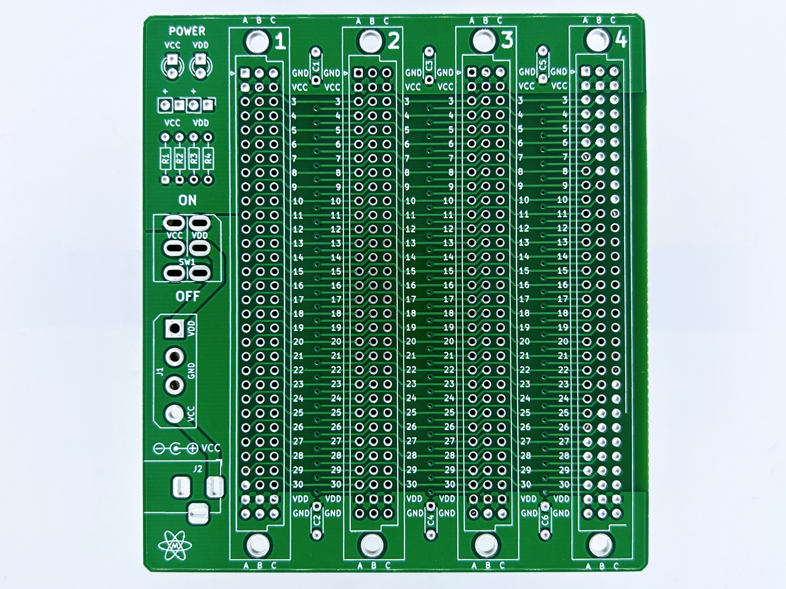
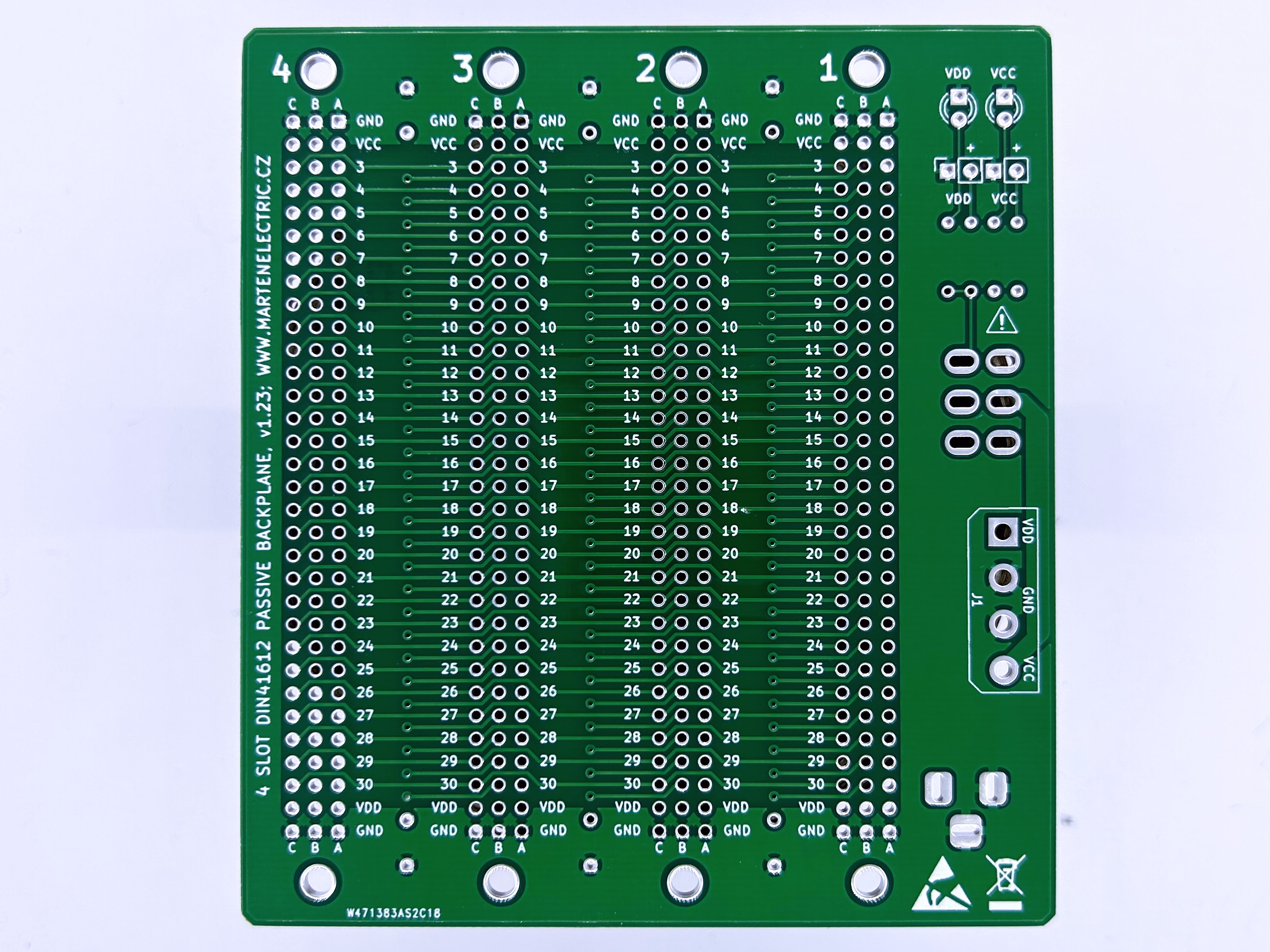
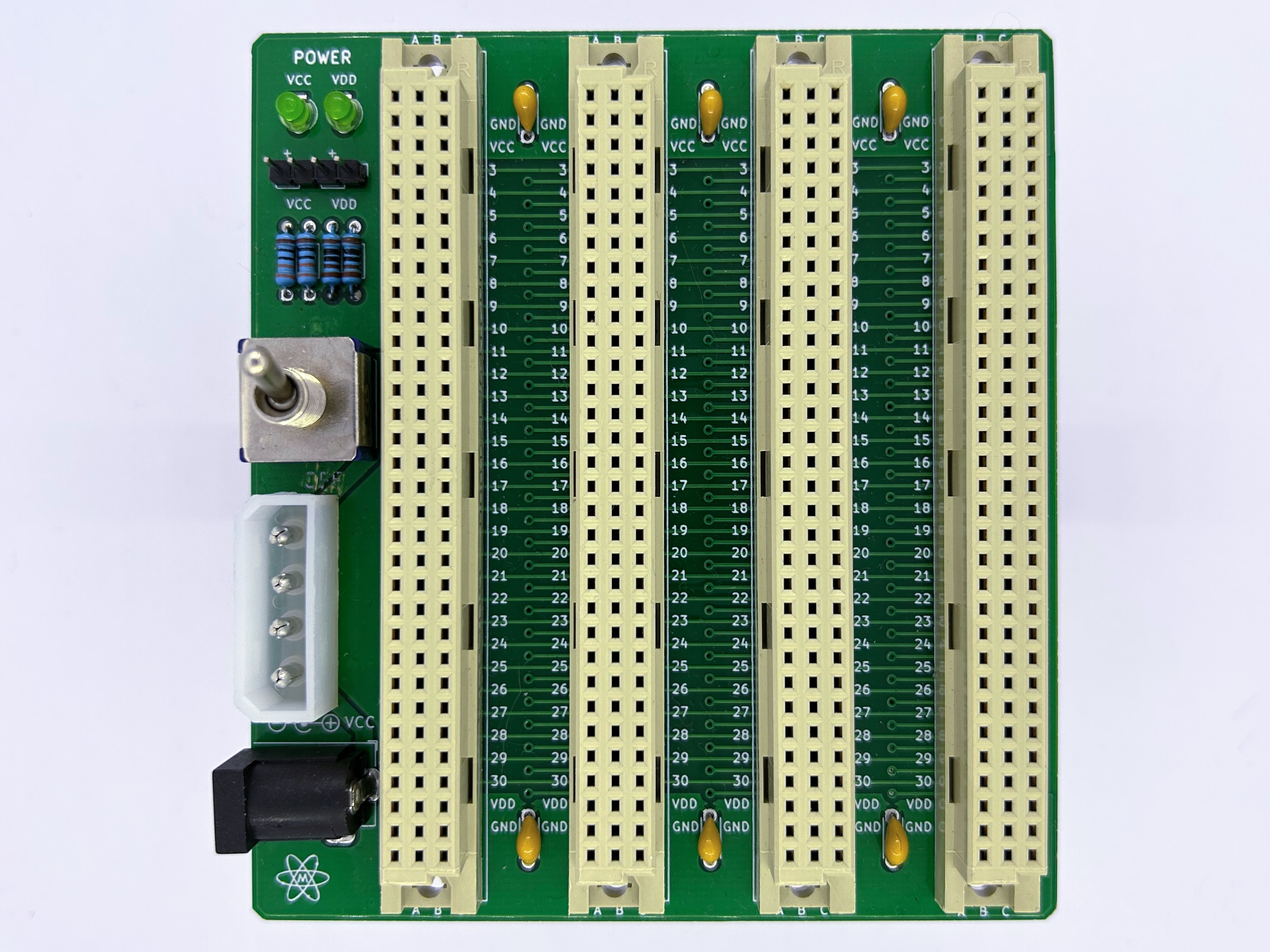
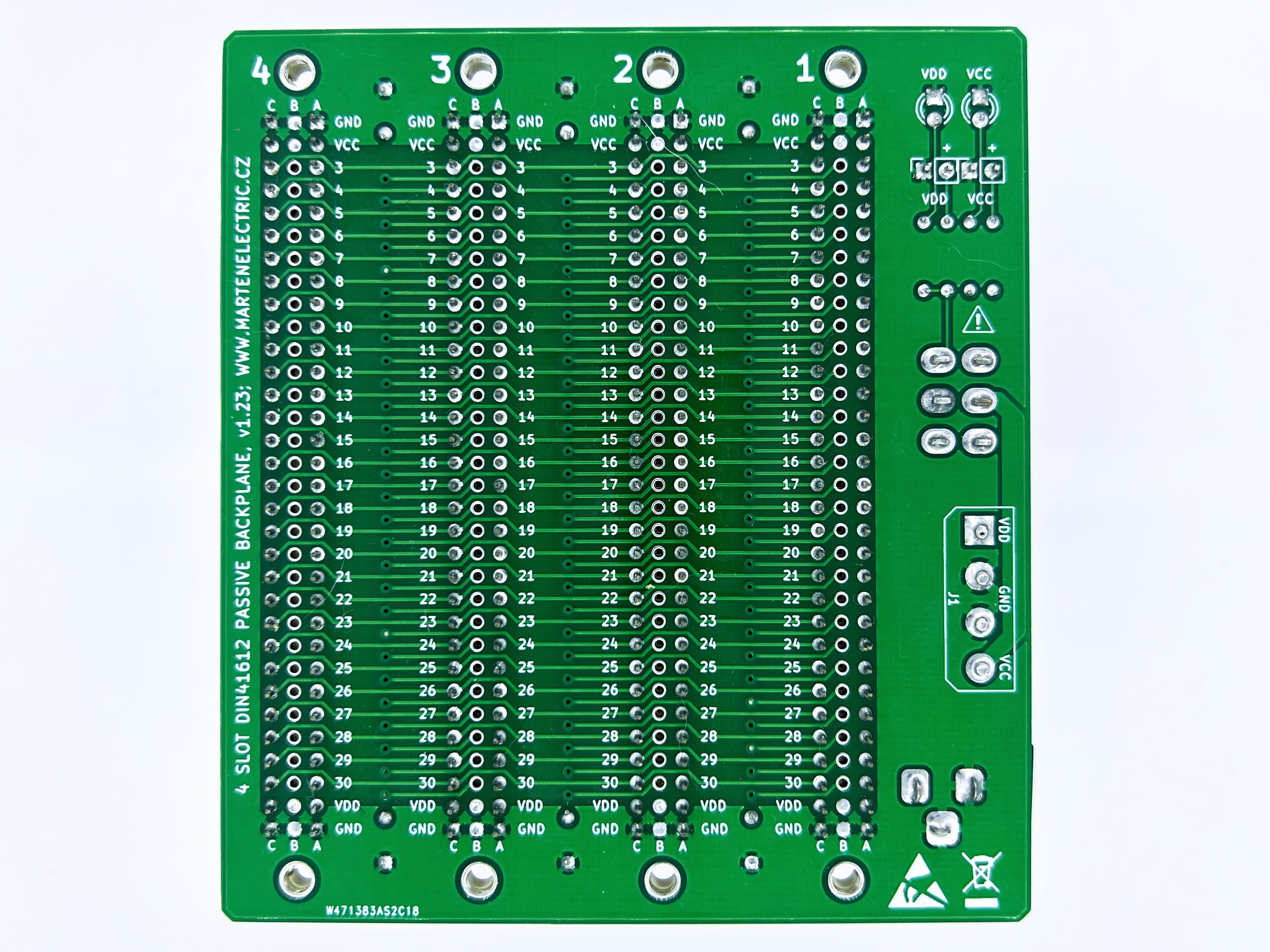
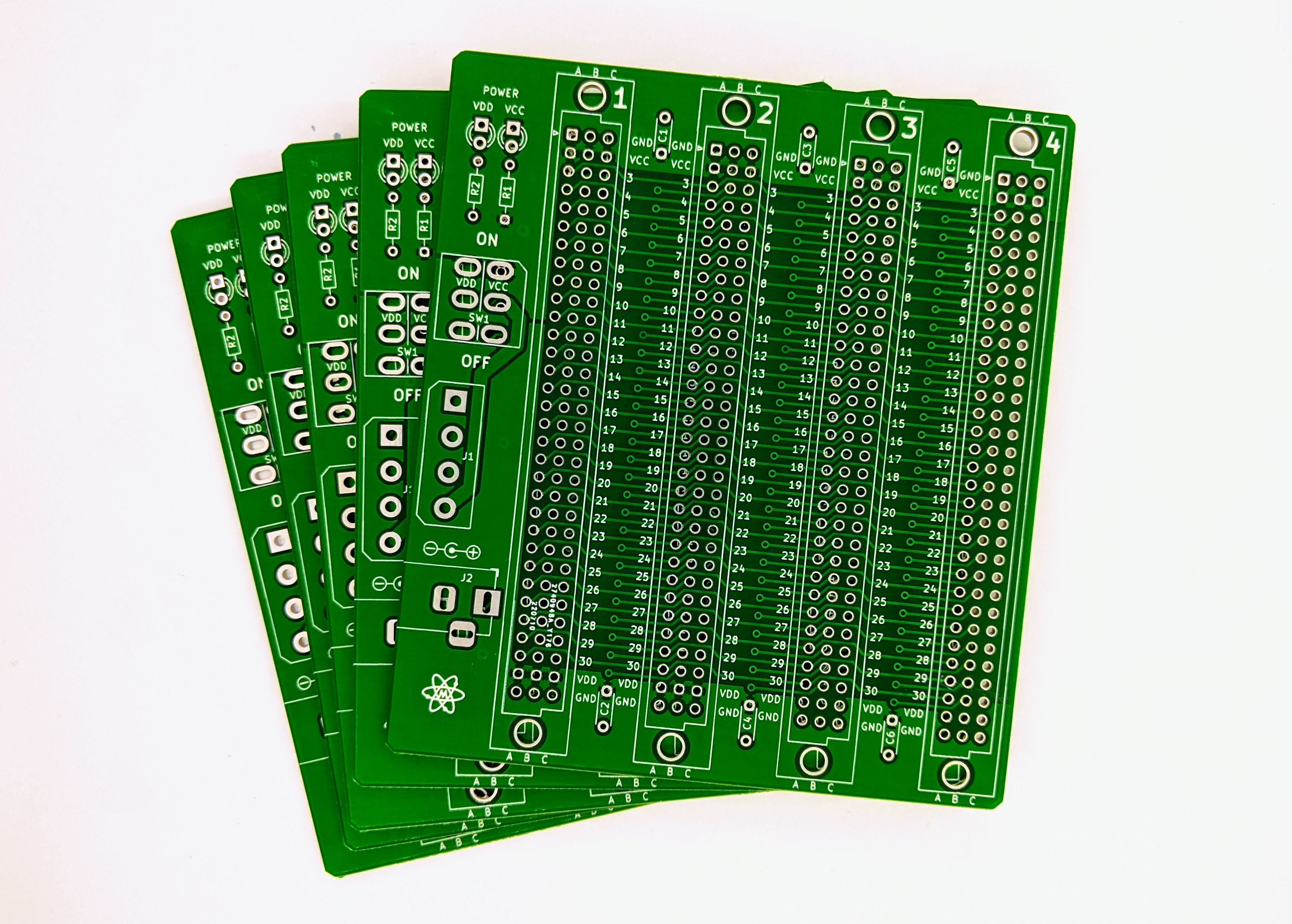
Photographs
click on pictures to enlarge
gerber files and photographs may vary, v1.23 pictured
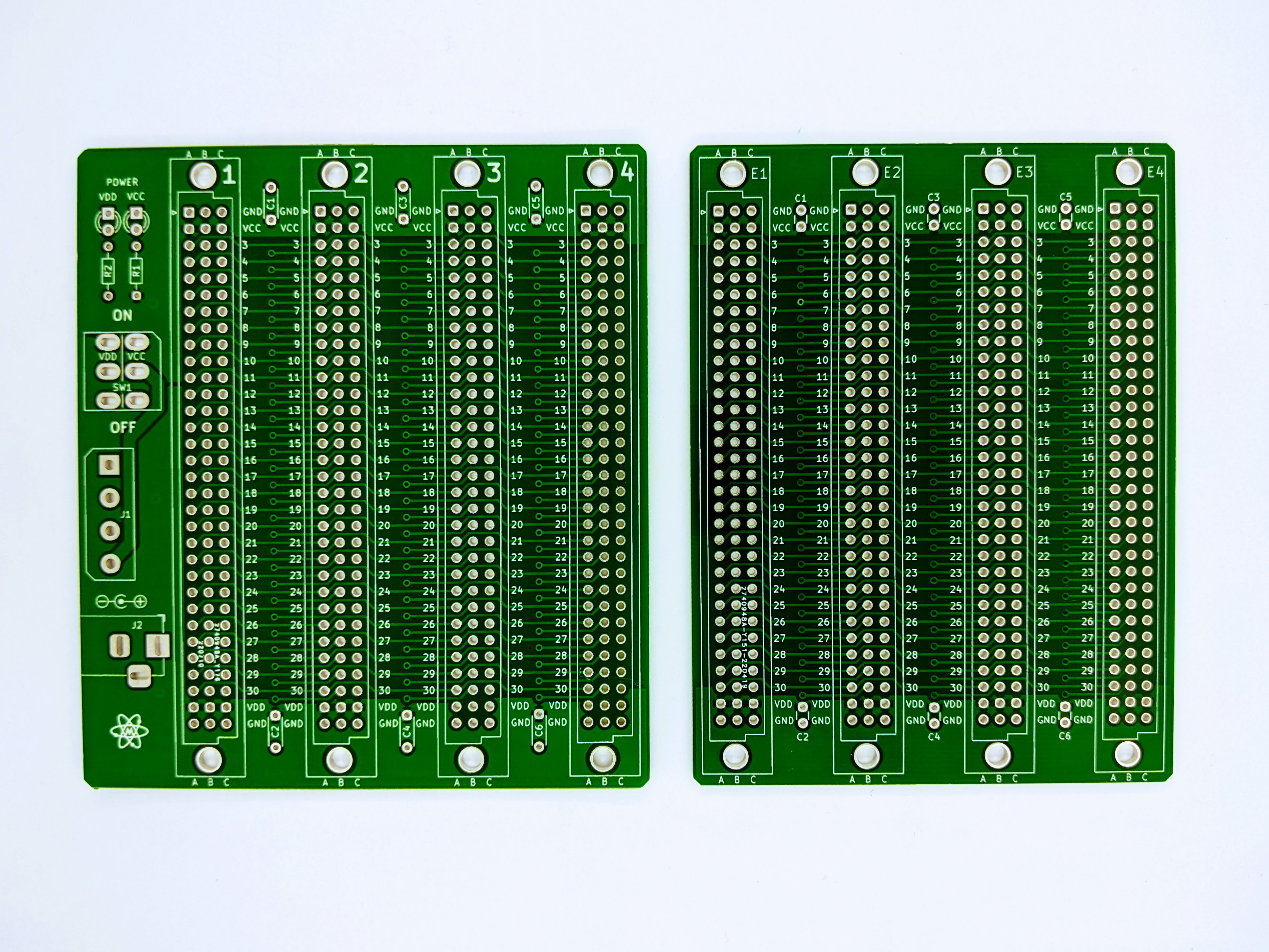
comparison between v1.1 and v1.2
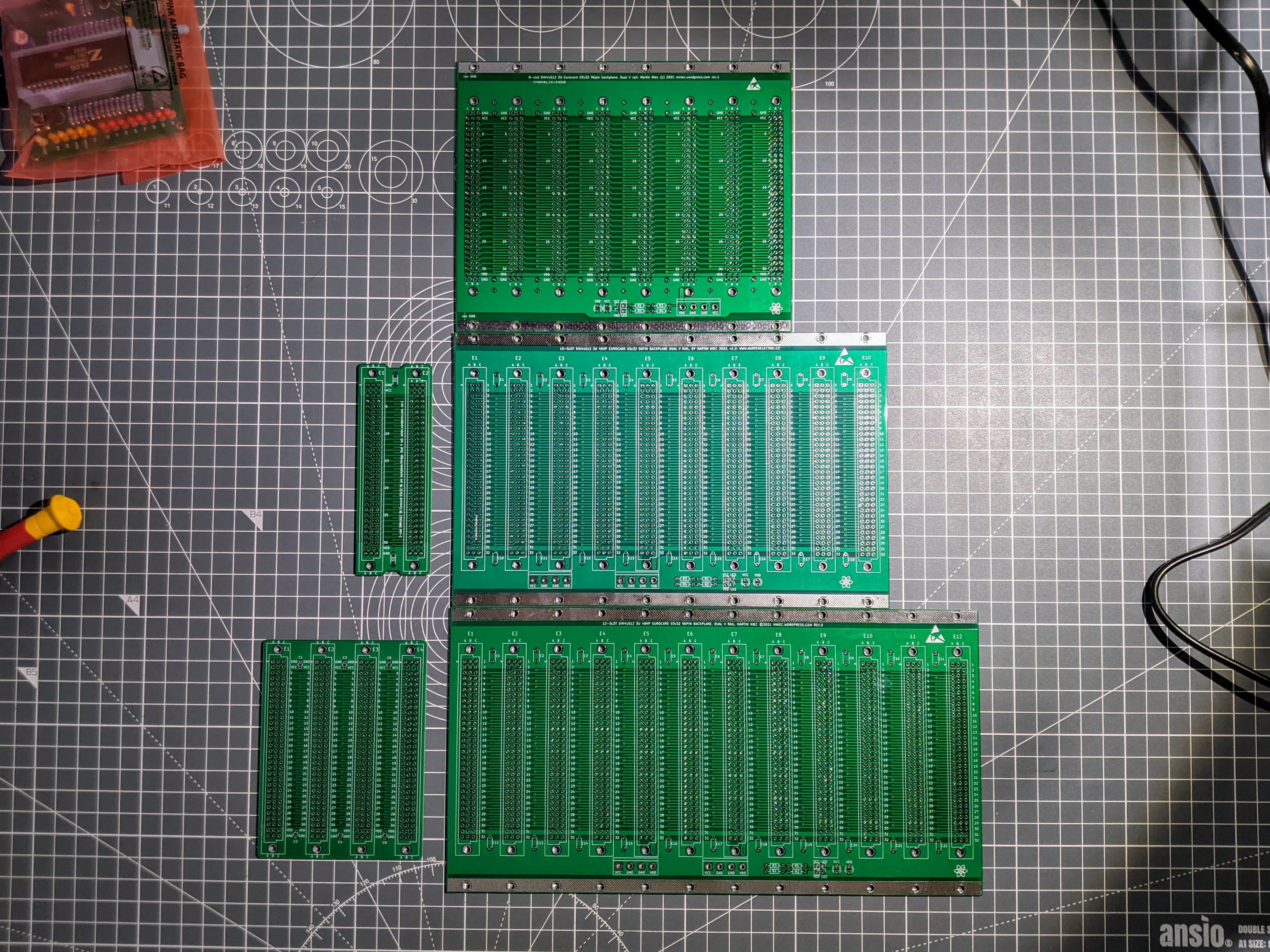
physical size comparison between different backplanes
Versions and revisions
This section lists the project version and revision history.
v1.24
■ Added headers for external power LED indicators
■ Minor silk screen updates
■ Minor PCB edge and copper fill updates
v1.21
■ Fixed connector positions and hole size
■ Swapped VDD and VCC connector and switch sides
■ Cosmetic changes
v1.2
■ Various silkscreen and cosmetic updates
■ Capacitor footprint changed
■ Added switch, molex connector and DC barrel jack.
■ Added LED's
v1.1
■ Various silkscreen updates
■ Various cosmetic updates
■ Added 45° chamfered corner edges